
Appendix D. CPS Menu Structure
W
ILD
C
ARD
I
ON/OFF
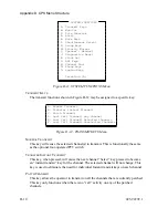
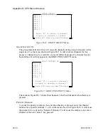
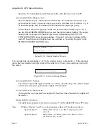
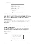
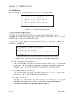
Toggle the Wild Card I function on the appropriate tone controlled radio channel.
Refer to Appendix A or B for the function actually transmitted.
W
ILD
C
ARD
II
ON/OFF
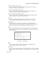
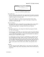
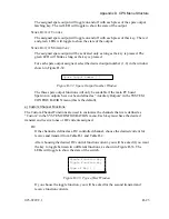
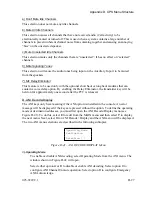
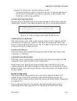
Toggle the Wild Card II function on the appropriate tone controlled radio channel.
Refer to Appendix A or B for the function actually transmitted.
d) Auxiliary Input/Output
As described in Section 4, “F. Input/Output Configuration”, I/O Port numbers 9-38 represent
any optional Expanded Aux. I/O Card(s) (Part No. 702-9448) installed in the console. These
port numbers can always be defined, but will only be meaningful if the appropriate Expanded
Aux. I/O cards are present in the system. Each card has six I/O ports, allowing a maximum of
five cards to be installed.
I/O port numbers 1-8 represent the standard main PC board Aux./Spare I/O Ports. If these I/O
ports are defined as “Spare” ports (instead of “Auxiliary”) in the System Configuration
section of the main Edit menu, then Auxiliary Input/Output port numbers 1-8 become
unavailable and cannot be selected from any auxiliary port number menu. Conversely, if
these I/O ports are defined as “Auxiliary” ports (instead of “Spare”) in the System
Configuration section of the main Edit menu, then Auxiliary Input/Output port numbers 1-8
are available but all Spare Input and/or Spare Output menu choices are suppressed and not
available.
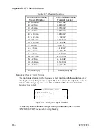
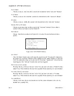
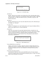
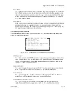
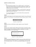
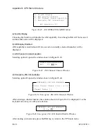
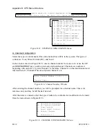
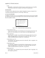
The menu in Figure D-26 shows the selections available for Input/Output functions.
A. Auxiliary Input
B. Auxiliary Output Interlocked
C. Auxiliary Output Toggle
D. Auxiliary Output Momentary
E. Spare Output Latching
F. Spare Output Toggle
G. Spare Output Momentary
Selection [B]
AUXILIARY INPUT / OUTPUT
Figure D-26. AUXILIARY INPUT/OUTPUT Menu
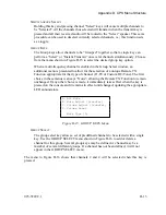
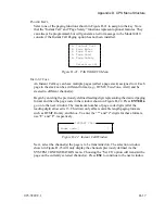
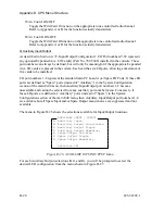
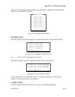
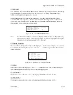
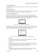
For each Auxiliary Output (selections
B
,
C
, and
D
), you will be prompted to select the
desired LED configuration from the menu shown in Figure D-27.
D-20
025-9229C.1
Summary of Contents for 4010
Page 2: ......
Page 4: ......
Page 7: ...1 INTRODUCTION HARDWARE REQUIREMENTS 1 1 DEFINITIONS 1 1 MANUALS 1 2...
Page 8: ......
Page 12: ......
Page 16: ...Section 2 Installation 2 4 025 9229C 1...
Page 18: ......
Page 34: ...Section 3 Tutorial 3 16 025 9229C 1...
Page 36: ......
Page 58: ......
Page 60: ......
Page 62: ......
Page 64: ......
Page 108: ...Appendix D CPS Menu Structure D 44 025 9229C 1...
Page 110: ......


