

Option Installation
48
Gooseneck Microphone
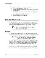
The Gooseneck Microphone (P/N 950-9314) may be used with the Model 4010 Console.
When installed in the field, the microphone will come with an adapter box to provide a
base for the mounting of the microphone.
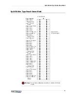
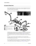
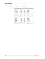
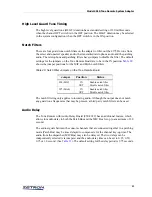
Figure 7: Gooseneck Microphone Assembly
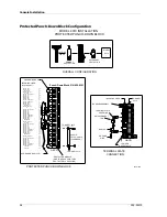
Installation requires opening the top cover, inserting the cable through the front hole of the
four mounting holes located on the left side of the unit (see
). The cable is then
drawn through the hole while positioning the mounting box studs in the other three
mounting holes. The nuts are used to secure the microphone adapter with the two threaded
studs.
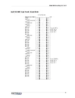
The cable is connected to P12 on the Control Board near the microphone adapter
mounting position. Pin 1 of the cable is the white wire and is connected to the P12, Pin 1,
which is nearest the rear of the console.
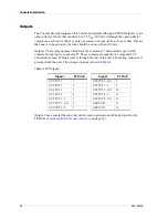
The system configuration normally uses the gooseneck microphone as the default audio
source. If the audio source has been changed (e.g., to a desk microphone), it is necessary
to use CPSW to modify the system configuration (see
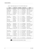
ITEM QTY PART NUMBER DESCRIPTION
Cut microphone wire to 7" from end of gooseneck. Strip
outer jacket of microphone wire 5" from end. Assemble
with parts 5 and 6.
Place threadlock on gooseneck mic threads.
Star washer and nut supplied with gooseneck.
Install wind sock (part of 305-0122) over end of
microphone.


