

Option Installation
58
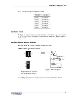
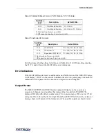
Table 15: Auxiliary Output Jumpers Explained
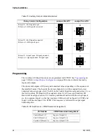
Programming
The Auxiliary I/O Board functions are programmed with CPSW. See
page 79. Refer to
on page 90 for more detail about using
inputs and outputs.
The inputs and outputs will be assigned numerical values depending on the sequence of
the installed boards. The board in the lowest channel slot will be assigned the lowest
numerical value in groups of six. The I/O on the Control Board are assigned values 1-8, so
the first Auxiliary I/O Board will be assigned values 9-14. The second Auxiliary I/O
Board will be assigned values 15-20 and any additional boards will follow in groups of
six. For example, Input 1 on the first Auxiliary I/O Board will be Input 9 to CPSW and
Input 2 will become Input 10 to CPSW. This sequence is followed for output signal
numbering also.
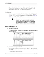
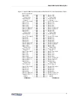
Table 16: I/O Numbers vs. CPSW Numerical Assignment
Relay Contact Configuration
Jumper Pair JPY
Jumper Pair JPX
Relay off, A & B signals open
Relay on, A & B signals connected
Relay off, A & B signals connected
Relay on, A & B signals open
Relay off, A signal open, B signal grounded
Relay on, A signal grounded, B signal open
A
B
A
D
C
B
A
B
A
D
C
B
A
B
A
D
C
B
I/O Number
CPSW Numerical Assignment
Control Board 1-8
Input or Output 1-8
First I/O Board 1-6
Input or Output 9-14
Second I/O Board 1-6
Input or Output 15-20


