

59
Model 4010 Auxiliary I/O Card
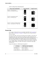
The sequence will continue for as many I/O boards as are installed.
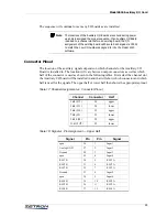
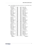
Connector Pinout
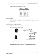
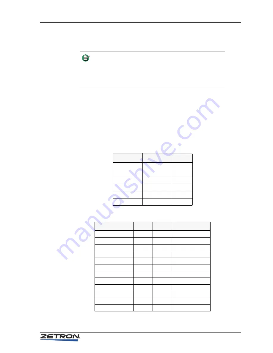
The location of the auxiliary signals depends on which channel slot the Auxiliary I/O
Board is installed in. The location will vary between output connectors as well as which
half of the connector is used as shown in the following tables. First select the channel slot
the Auxiliary I/O board will be installed in and that will show which connector and which
half is used for the signals. The upper half or lower half then shows the appropriate pinout.
Table 17: Channel Assignment vs. Connector Pinout
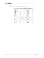
Table 18: Signal vs. Pin Assignment — Upper Half
Note
The locations of the Auxiliary I/O Boards are sensed during power
up and are assigned the proper sequence. If an Auxiliary I/O Board
is added to a channel slot before an existing board, the I/O
assignment of the existing board will have to be changed via CPSW
to match the new I/O numbers assigned to it by the Model 4010
software.
Channel
Connector
Half
1&2 (J12)
J4
upper
3&4 (J11)
J4
lower
5&6 (J10)
J3
upper
7&8 (J9)
J3
lower
9&10 (J8)
J2
upper
11&12 (J7)
J2
lower
Signal
Pin
Pin
Signal
open
26
1
Input 1
Analog GND
27
2
Input 2
Ground
28
3
Input 3
open
29
4
Input 4
RLY1B
30
5
RLY1A
RLY2B
31
6
RLY2A
RLY3B
32
7
RLY3A
Ground
33
8
Input 5
open
34
9
Input 6
RLY4B
35
10
RLY4A
RLY5B
36
11
RLY5A
RLY6B
37
12
RLY6A


