ZETRON 4010, Installation And Programming
The Black & Decker 4010 is a versatile and reliable tool that is essential for any DIY enthusiast. With its durable construction and powerful performance, this tool is designed to tackle a wide range of tasks. Download the free Owner's Manual from 88.208.23.73:8080 to unleash the full potential of this exceptional product.
Share
Download
Reviews:
No comments
Related manuals for 4010

500 Series
Brand: OceanAudio Pages: 2

MS-100
Brand: MAKINEX Pages: 16

4010
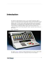
Brand: ZETRON Pages: 123

3
Brand: Teac Pages: 22

KGS
Brand: Danfoss Pages: 10

Powerhead PA Mixer
Brand: KAM Pages: 4

CL3
Brand: Yamaha Pages: 65

CL3
Brand: Yamaha Pages: 401

TM300
Brand: Samson Pages: 58

PYD1030
Brand: Pyle Pages: 8

AG-HMX100
Brand: Panasonic Pages: 37

Ramsa WR-DA7 mkII
Brand: Panasonic Pages: 63

6100 Series
Brand: Tapco Pages: 25

MW10
Brand: Yamaha Pages: 36

Apollo
Brand: Calrec Pages: 124

CD100
Brand: Laney Pages: 20

40 Series
Brand: Bailey Pages: 103

Xenon
Brand: DAPAudio Pages: 18


