11. Attach the 24 in. –3 AN hose, with the red ends, to the fuel solenoid outlet. Attach the other end of this line
to the fuel distribution block’s jet fitting. Attach the 24 in. –3 AN hose, with the purple ends, to the nitrous
solenoid outlet. Attach the other end of this line to the nitrous distribution block’s jet fitting.
12. Attach the –4AN nitrous delivery line, from the bottle, to the nitrous solenoid inlet.
13. Provide a source of fuel from the fuel rail that will connect to the 3 ft. long -4AN hose. If needed, a -4AN
to 1/8NPT fitting is supplied. Drill and tap the fuel rail for this fitting. Make sure all metal shavings are
removed before reinstalling the fuel rail.
14. Attach the 3ft., -4AN fuel delivery line, from the fuel source, to the
fuel solenoid inlet.
Step 5: Wiring
1. Mount the arming switch in an easily accessible area for the driver.
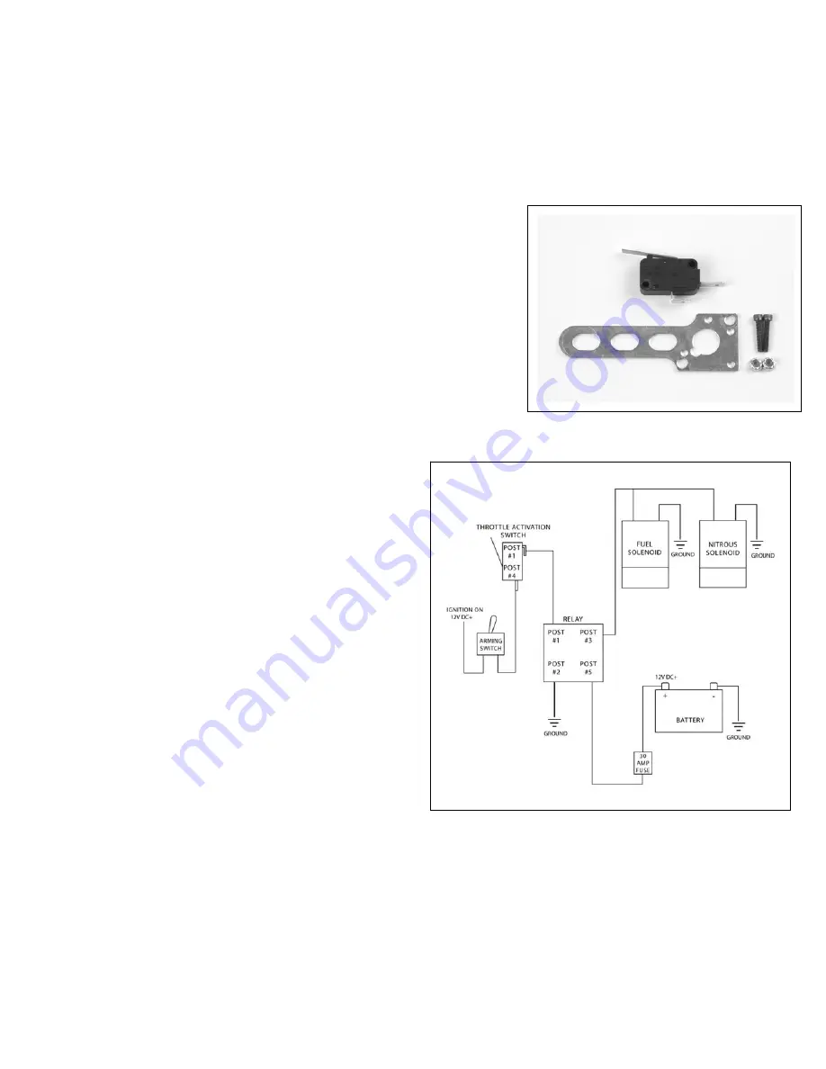
2. Assemble the throttle activation switch to the throttle switch bracket
using the 4-40 bolts and nylon lock nuts (see Fig. 7). Do not
overtighten the bolts, damage to the throttle activation switch can result.
3. The throttle switch bracket is made of easily formed
material. Attach the end of the bracket to one of the
throttle body studs and bend the bracket in such a way as
to allow the engine’s throttle arm to contact and depress
the switch lever at wide open throttle.
4. Using the supplied electrical connectors and wire,
refer to the wiring diagram for proper routing and
electrical connections for the nitrous system (see Fig. 8).
Always use the supplied fuse for electrical system
protection in the event of a short in the system. The best
positive (+) power source for the nitrous system is a
direct connection to the battery’s positive (+) post. Do not splice into the factory wire harness, it will not have
the ability to supply the current required by the nitrous and fuel solenoids.
Step 6: Check Fuel and Nitrous Pressure Lines
1. Perform a final inspection of all plumbing and electrical connections to ensure that they are correct.
Fig. 7
Fig. 8


