SET UP
Page5-27
03
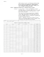
- Normal, No Current when at Lock-up. Preset
for ZF220-550, 24VDC Systems.
04
- Normal, No Current when at Lock-up. Preset
for ZF2000, 24 VDC Systems.
05
- Inverse, No Current when at Lock-up. Preset
for ZF670, 1900 or 2500, 24VDC Systems.
06
- Preset for 12VDC ZF Hurth Systems.
07
- Preset for 24VDC ZF Hurth Systems.
The default value is
00
.
5-6.5.4.2 Function Code
L2
– Troll Minimum Pressure
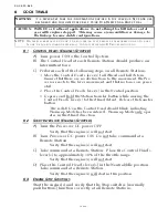
This Function fine tunes the amount of current deliv-
ered to the proportional solenoid, so that clutch pres-
sure is at the minimum point where shaft rotations
are still possible.
The hydraulic pressure on the Clutch plate can typi-
cally be decreased to a point where the shaft is rotat-
ing at 30% to 50% of normal shaft RPM at Idle.
The available Values are
0.00
to
80.0
percent of the
maximum current available. The Default Value is
10.0
%. The Value selected must always be at least
20% below or above (Normal/Inverted) the value
selected with Troll Maximum Pressure
L3
.
5-6.5.4.3 Function Code
L3
– Troll Maximum Pressure
This Function fine tunes the amount of current deliv-
ered to the proportional solenoid, so that clutch pres-
sure is at the maximum point prior to Clutch Plate
lock-up.
The hydraulic pressure on the Clutch plate can typi-
cally be decreased to a point where the shaft is rotat-
ing at approximately 70% of normal shaft RPM at
Idle. Attempts to increase pressure above this point
typically results in Clutch Plate lock-up.
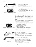
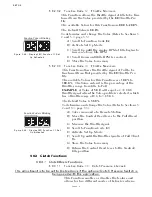
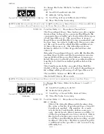
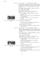
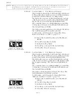
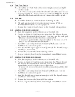
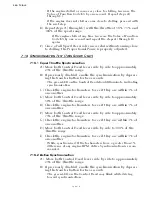
Figure 5-54: Display LED
Function L1 Set Up Activated
To determine, and if required, change the Value
(Refer to Sections 5-2 and 5-3, page 5-5):
A)Scroll to Function Code
L1
.
B) Activate Set Up Mode.
C) Scroll Up or Down to the appropriate Value for
the Trolling Valve.
D) Store the Value to memory
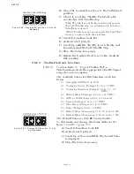
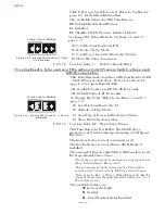
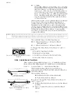
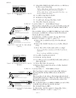
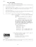
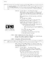
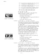
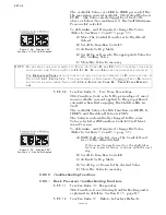
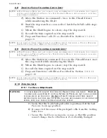
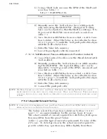
Figure 5-55: Display LED
Function L2 Set Up Activated
To determine, and if required, change the Value
(Refer to Sections5-2 and 5-3, page 5-5):
A)Move the Control Head lever to the Ahead
detent.
B) Scroll to Function Code
L2
.
C) Activate Set Up Mode.
D) Scroll Up or Down to the appropriate Value for
the Trolling Valve.
E) Store the Value to memory
Summary of Contents for ClearCommand 9000 Series
Page 132: ......
Page 133: ...APPENDIX A...
Page 134: ......
Page 139: ......
Page 140: ...Page A 4...
Page 143: ......
Page 144: ...10...
Page 148: ...Page A 18...
Page 149: ...Page A 19 TEMPLATE...
Page 150: ...Page A 20...
Page 152: ...Page A 22...
Page 154: ...Page A 24...
Page 156: ...Page A 26...
Page 157: ...Page A 27 Drawing 11488D 1 Twin Screw Single APS Connection Alternate Remote Switch...
Page 158: ...Page A 28...
Page 159: ...Page A 29 Drawing 11488D 2 Twin Screw Dual APS Connections...
Page 160: ...Page A 30...
Page 161: ...Page A 31 Drawing 11488D 3 APS Notes Page...
Page 162: ...Page A 32...
Page 164: ...Page A 34...
Page 166: ...Page A 36...
Page 170: ...Page A 40...
Page 172: ...Page A 42...
Page 176: ...Page A 46...
Page 178: ...Page C 48 ZF Mathers LLC 12125 Harbour Reach Drive Suite B Mukilteo WA 98275...
Page 179: ...APPENDIX B...
Page 180: ......
Page 234: ...Appendix B 6...
Page 238: ...Appendix B 10...
Page 242: ...Appendix B 14...
Page 247: ...Service Field Test Unit Reference Manual MM13927 Rev E 4 07...
Page 248: ......
Page 250: ...Page ii Table of Contents...
Page 264: ...SERVICE FIELD TEST UNIT MM13927 RvD 10 03 Page 3 2...
Page 265: ...APPENDIX C...
Page 266: ......
Page 267: ...Appendix C 1 Drawing 12284A 1 ClearCommand Diagram all options...
Page 268: ...Appendix C 2...
Page 269: ...Appendix C 3 Drawing 12284A 2 ClearCommand Circuit Board Connections...
Page 270: ...Appendix C 4...
Page 271: ...Appendix C 5 Drawing 12284A 3 ClearCommand Drawing Notes Page...
Page 272: ...Appendix C 6...

