DOCK TRIALS
Page6-2
6-4 P
USH
-P
ULL
C
ABLES
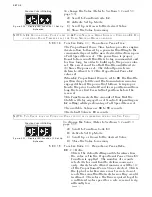
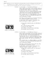
A) Check that all Push-Pull cable connecting fasteners are tight-
ened securely.
B) In the Processor(s) check that the Push-Pull cable jam nuts are
securely tightened. A loose hex nut can back off the Push-Pull
cable threaded end and effectively change the cable length.
6-5 H
IGH
I
DLE
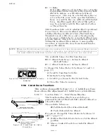
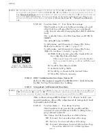
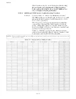
A) Place the Station in command into Warm-up Mode.
B) Adjust Function Code E6 to the desired engine RPM, as
described in Section 5-5.2.6.2, page 5-9.
C) Return the Control Head’s lever to the Neutral/Idle position.
6-6 C
ONTROL
H
EAD
S
ERVO
C
OMMAND
A) Start the engine(s) and let them run at Neutral/Idle.
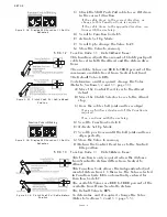
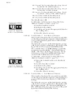
B) Place one Control Head lever at a time into the Ahead detent,
the Astern detent and then Neutral. Confirm that the push-pull
cable movement is in the direction commanded.
• If incorrect, perform the steps described in Section 5-5.2.7.6,
page 5-10, for transmission push-pull.
C) Place the Control System into Warm-Up Mode and confirm
that there is control of speed.
D) Run the throttle up to approximately 20% of the throttle range
for at least 10 seconds.
E) Return the lever to the Neutral/Idle position.
F) Repeat steps A) thru E) at the remaining Control Head levers.
6-7 C
ONTROL
H
EAD
S
OLENOID
C
OMMAND
A) Start the engine(s) and let them run at Neutral/Idle.
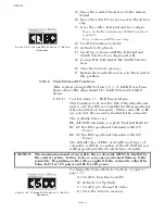
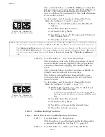
B) Place one Control Head lever at a time into the Ahead detent,
the Astern detent and then Neutral. Confirm that the move-
ment of the vessel is in the correct direction.
• If incorrect, reverse the electric cable connections at the shift
solenoids.
C) Place the Control System into Warm-Up Mode and confirm
that there is control of speed.
D) Run the throttle up to approximately 20% of the throttle range
for at least 10 seconds.
E) Return the lever to the Neutral/Idle position.
F) Repeat steps A) thru E) at the remaining Control Head levers.
Summary of Contents for ClearCommand 9000 Series
Page 132: ......
Page 133: ...APPENDIX A...
Page 134: ......
Page 139: ......
Page 140: ...Page A 4...
Page 143: ......
Page 144: ...10...
Page 148: ...Page A 18...
Page 149: ...Page A 19 TEMPLATE...
Page 150: ...Page A 20...
Page 152: ...Page A 22...
Page 154: ...Page A 24...
Page 156: ...Page A 26...
Page 157: ...Page A 27 Drawing 11488D 1 Twin Screw Single APS Connection Alternate Remote Switch...
Page 158: ...Page A 28...
Page 159: ...Page A 29 Drawing 11488D 2 Twin Screw Dual APS Connections...
Page 160: ...Page A 30...
Page 161: ...Page A 31 Drawing 11488D 3 APS Notes Page...
Page 162: ...Page A 32...
Page 164: ...Page A 34...
Page 166: ...Page A 36...
Page 170: ...Page A 40...
Page 172: ...Page A 42...
Page 176: ...Page A 46...
Page 178: ...Page C 48 ZF Mathers LLC 12125 Harbour Reach Drive Suite B Mukilteo WA 98275...
Page 179: ...APPENDIX B...
Page 180: ......
Page 234: ...Appendix B 6...
Page 238: ...Appendix B 10...
Page 242: ...Appendix B 14...
Page 247: ...Service Field Test Unit Reference Manual MM13927 Rev E 4 07...
Page 248: ......
Page 250: ...Page ii Table of Contents...
Page 264: ...SERVICE FIELD TEST UNIT MM13927 RvD 10 03 Page 3 2...
Page 265: ...APPENDIX C...
Page 266: ......
Page 267: ...Appendix C 1 Drawing 12284A 1 ClearCommand Diagram all options...
Page 268: ...Appendix C 2...
Page 269: ...Appendix C 3 Drawing 12284A 2 ClearCommand Circuit Board Connections...
Page 270: ...Appendix C 4...
Page 271: ...Appendix C 5 Drawing 12284A 3 ClearCommand Drawing Notes Page...
Page 272: ...Appendix C 6...

