SEA TRIALS
Page7-1
7
SEA TRIALS
7-11 F
ULL
S
PEED
S
ETTING
- S
ERVO
T
HROTTLE
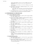
A) Warm-up the engine(s) and transmission(s) and slowly move
into open water.
B) Gradually move the lever(s) to Full speed.
C) If synchronization is installed, disable synchronization as
explained in Section 2-10.4, page 2-7.
• If the engine RPM is low, check whether the engine throttle lever
is against the full speed stop.
• If the engine RPM is high, decrease by using Function Code E3, as
explained in Section 5-6.2.2.3, page 5-17.
D) For twin screw applications, check that matching Idle, Mid-
range and Full speed Control Head lever positions cause equal
RPM in both engines.
• If RPM’s do not match, check push-pull cable travel. If travel does
not match when the Control Head levers are side by side, adjust
Function Code E3 Throttle Maximum, refer to Section 5-6.2.2.3,
page 5-17.
7-12 F
ULL
S
PEED
S
ETTING
- E
LECTRONIC
T
HROTTLE
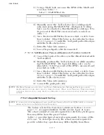
A) Warm-up the engine(s) and transmission(s) and slowly move
into open water.
B) Gradually move the lever(s) to Full speed.
C) If synchronization is installed, disable synchronization as
explained in Section 5-6.2.1.5, page 5-16.
• If the engine RPM is low, refer to Appendix B, MM13927 Rev.C 4/
03 Service Field Test Unit Manual.
• If the engine RPM is high, decrease by using Function Code
E3
, as
explained in Section 5-6.2.3.3, page 5-20.
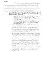
D) For twin screw applications, check that matching Idle, Mid-
range and Full speed Control Head lever positions cause equal
RPM in both engines.
WARNING: I
T
IS
IMPERATIVE
THAT
THE
INFORMATION
PROVIDED
IN
THE
PREVIOUS
S
ECTIONS
HAS
BEEN
READ
AND
FOLLOWED
PRECISELY
,
PRIOR
TO
ATTEMPTING
A
S
EA
T
RIAL
. I
F
ANY
OF
THE
FOLLOWING
TESTS
FAIL
,
DISCONTINUE
THE
S
EA
T
RIAL
IMMEDIATELY
AND
RETURN
TO
THE
DOCK
. C
ONSULT
A
PPENDIX
B T
ROUBLESHOOTING
S
ECTION
OR
A
ZF
F
ACILITY
PRIOR
TO
RESUMING
THE
S
EA
T
RIAL
.
NOTE: O
N
TWIN
SCREW
APPLICATIONS
,
THE
FOLLOWING
TESTS
MUST
BE
PERFORMED
ON
BOTH
SIDES
.
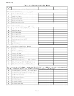
D
URING
THE
COURSE
OF
THE
D
OCK
T
RIAL
AND
S
EA
T
RIALS
,
FILL
OUT
THE
T
RIAL
R
EPORT
.
R
ETAIN
THIS
INFORMATION
FOR
FUTURE
USE
.
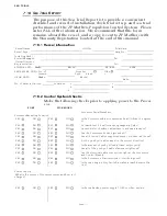
Summary of Contents for ClearCommand 9000 Series
Page 132: ......
Page 133: ...APPENDIX A...
Page 134: ......
Page 139: ......
Page 140: ...Page A 4...
Page 143: ......
Page 144: ...10...
Page 148: ...Page A 18...
Page 149: ...Page A 19 TEMPLATE...
Page 150: ...Page A 20...
Page 152: ...Page A 22...
Page 154: ...Page A 24...
Page 156: ...Page A 26...
Page 157: ...Page A 27 Drawing 11488D 1 Twin Screw Single APS Connection Alternate Remote Switch...
Page 158: ...Page A 28...
Page 159: ...Page A 29 Drawing 11488D 2 Twin Screw Dual APS Connections...
Page 160: ...Page A 30...
Page 161: ...Page A 31 Drawing 11488D 3 APS Notes Page...
Page 162: ...Page A 32...
Page 164: ...Page A 34...
Page 166: ...Page A 36...
Page 170: ...Page A 40...
Page 172: ...Page A 42...
Page 176: ...Page A 46...
Page 178: ...Page C 48 ZF Mathers LLC 12125 Harbour Reach Drive Suite B Mukilteo WA 98275...
Page 179: ...APPENDIX B...
Page 180: ......
Page 234: ...Appendix B 6...
Page 238: ...Appendix B 10...
Page 242: ...Appendix B 14...
Page 247: ...Service Field Test Unit Reference Manual MM13927 Rev E 4 07...
Page 248: ......
Page 250: ...Page ii Table of Contents...
Page 264: ...SERVICE FIELD TEST UNIT MM13927 RvD 10 03 Page 3 2...
Page 265: ...APPENDIX C...
Page 266: ......
Page 267: ...Appendix C 1 Drawing 12284A 1 ClearCommand Diagram all options...
Page 268: ...Appendix C 2...
Page 269: ...Appendix C 3 Drawing 12284A 2 ClearCommand Circuit Board Connections...
Page 270: ...Appendix C 4...
Page 271: ...Appendix C 5 Drawing 12284A 3 ClearCommand Drawing Notes Page...
Page 272: ...Appendix C 6...

