CONTROL OPTIONS
Page8-4
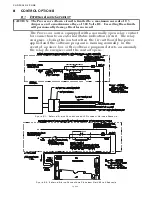
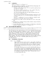
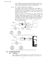
A) Install a Shuttle Valve on or near the Transmission.
B) Connect hydraulic line from the Ahead and Astern
Clutches.
C) Connect a hydraulic line that is no longer than 5 feet
(1,524m)and at approximately the same height between the
Shuttle Valve and the Pressure Switch.
D) Connect the Power Wire Harness’s Clutch Pressure Inter-
lock cable to the Pressure Switch’s normally open contact.
E) Calibrate the Pressure Switch to close when adequate
Clutch Pressure is reached. (Refer to the Transmission
manufactures Installation Manual)
The Processor allows up to five Remote Stations. The SE allows up
to an additional four Remote Stations for a total of nine Stations.
The SE and Processor communicate via the Serial Communication
cable. Control Heads connected to the SE offer all of the function-
ality of a standard Remote Station.
For detailed information on the operation, installation and adjust-
ment of the SE, refer to the Station Expander Installation Manual
supplied with the Expander.
8-4 9001 A
CTUATOR
T
ROLLING
V
ALVE
C
ONTROL
Most Marine Transmissions offer an optional Trolling Valve. A
Trolling Valve controls the amount of pressure applied to the
Clutch Plate. By doing so, the speed of the propeller can be
reduced without decreasing engine RPM.
The Processor allows the operator to control, with a single lever,
the Trolling Valve, Clutch and Throttle. In order to do so, a sepa-
rate Trolling Actuator [p/n 9001] must be installed.
The Trolling Actuator and the main Processor(s) communicate
with one another via the Serial Communication cable. The Troll-
ing Actuator contains two Servos, which allows the control of two
Trolling Valves with a single Actuator. This option is available only
for Processors that do not have Integrated Servo or Solenoid Troll-
ing.
For detailed information on the operation, installation and adjust-
ment of the Trolling Actuator, refer to the Trolling Actuator Instal-
lation Manual supplied with the Actuator.
Summary of Contents for ClearCommand 9000 Series
Page 132: ......
Page 133: ...APPENDIX A...
Page 134: ......
Page 139: ......
Page 140: ...Page A 4...
Page 143: ......
Page 144: ...10...
Page 148: ...Page A 18...
Page 149: ...Page A 19 TEMPLATE...
Page 150: ...Page A 20...
Page 152: ...Page A 22...
Page 154: ...Page A 24...
Page 156: ...Page A 26...
Page 157: ...Page A 27 Drawing 11488D 1 Twin Screw Single APS Connection Alternate Remote Switch...
Page 158: ...Page A 28...
Page 159: ...Page A 29 Drawing 11488D 2 Twin Screw Dual APS Connections...
Page 160: ...Page A 30...
Page 161: ...Page A 31 Drawing 11488D 3 APS Notes Page...
Page 162: ...Page A 32...
Page 164: ...Page A 34...
Page 166: ...Page A 36...
Page 170: ...Page A 40...
Page 172: ...Page A 42...
Page 176: ...Page A 46...
Page 178: ...Page C 48 ZF Mathers LLC 12125 Harbour Reach Drive Suite B Mukilteo WA 98275...
Page 179: ...APPENDIX B...
Page 180: ......
Page 234: ...Appendix B 6...
Page 238: ...Appendix B 10...
Page 242: ...Appendix B 14...
Page 247: ...Service Field Test Unit Reference Manual MM13927 Rev E 4 07...
Page 248: ......
Page 250: ...Page ii Table of Contents...
Page 264: ...SERVICE FIELD TEST UNIT MM13927 RvD 10 03 Page 3 2...
Page 265: ...APPENDIX C...
Page 266: ......
Page 267: ...Appendix C 1 Drawing 12284A 1 ClearCommand Diagram all options...
Page 268: ...Appendix C 2...
Page 269: ...Appendix C 3 Drawing 12284A 2 ClearCommand Circuit Board Connections...
Page 270: ...Appendix C 4...
Page 271: ...Appendix C 5 Drawing 12284A 3 ClearCommand Drawing Notes Page...
Page 272: ...Appendix C 6...

