background image

Page A-36

Summary of Contents for ClearCommand 9000 Series

Page 1: ...ClearCommand 9000 Series Installation Operation and Troubleshooting Manual MM9000 I Rev C 2 5 08...

Page 2: ...et a public network by satellite or otherwise without the prior written permission of ZF Marine Electronics LLC 12125 Harbour Reach Drive Suite B Mukilteo WA 98275 Legal Information The information in...

Page 3: ...X Servo 2 Table Preface 1 ClearCommand Processor List NOTE CONTAINS HELPFUL INFORMATION CAUTION Damage to the equipment may occur if these messages are not followed WARNING PERSONAL INJURY MAY RESULT...

Page 4: ...PREFACE Preface 2 Hard wired installation is described in Section 4 4 with the exception of the Tachometer Signal and Serial Communication Pigtails which always come from the factory pre wired...

Page 5: ...onal System Features Section 2 16 1 7 2 OPERATION 2 1 2 1 DC Power On 2 1 2 2 Taking Command 2 1 Figure 2 1 Station taking Command 2 1 2 3 Basic Operation 2 2 2 3 1 Normal Operating Mode 2 2 Figure 2...

Page 6: ...14 2 13 1 4 FIVE 5 SECOND STEADY TONE 2 14 Figure 2 17 Five 5 Second Steady Tone 2 14 2 13 1 5 THREE 3 SECOND STEADY TONE 2 14 Figure 2 18 Three 3 Second Steady Tone 2 14 2 13 1 6 FIVE SECONDS ON FIVE...

Page 7: ...l Harnesses 3 4 3 1 4 1 THROTTLE HARNESS 3 4 3 1 4 2 CLUTCH HARNESS 3 4 3 1 4 3 CLUTCH TROLL HARNESS 3 4 3 1 5 Standard Electric Cables 3 5 3 1 5 1 CONTROL HEAD ELECTRIC CABLE 3 5 3 1 5 2 POWER START...

Page 8: ...7 9120 and 9121 Enclosure Cable Holes 4 7 4 4 4 2 9122 CLUTCH TROLL SOLENOID CABLE HOLE LOCATIONS 4 7 Figure 4 8 9122 Enclosure Cable Holes 4 7 4 4 4 3 9210 AND 9211 THROTTLE ELECTRONIC CABLE HOLE LOC...

Page 9: ...20 5 SET UP PROCEDURE 5 1 5 1 Processor Components Used In Set Up 5 1 Figure 5 1 Typical Processor Cover 5 1 Figure 5 2 Processor Shield Push Button and Display LED Locations 5 1 5 1 1 Processor Disp...

Page 10: ...BASIC FUNCTIONS 5 15 5 6 3 1 1 Function Code C0 Clutch Pressure Interlock 5 15 Figure 5 30 Display LED Function C0 Set Up Activated 5 16 5 6 3 1 2 Function Code C1 Clutch Interlock Delay 5 16 Figure 5...

Page 11: ...tion Code H0 Diagnostics 5 28 5 6 5 1 2 Function Code H1 Return to Factory Defaults 5 28 5 6 5 2 ADDITIONAL 9000 SERIES TROUBLESHOOTING FUNCTION 5 29 5 6 5 2 1 Function Code H2 Driver Fault Detection...

Page 12: ...EGULARITIES 7 14 8 CONTROL OPTIONS 8 1 8 1 External Alarm Capability 8 1 Figure 8 1 External Alarm Connections with Processor Harness Example 8 1 Figure 8 2 External Alarm Connections Processor Hard W...

Page 13: ...ronic Propulsion Control Systems Three Year Limited Warranty MMC 163 Rev B 1 01 C 47 Warranty Registration Appendix B B1 TROUBLESHOOTING GENERAL B1 1 B1 1 Control Systems Examples B1 1 B1 1 1 9120 Thr...

Page 14: ...Tones B5 2 Figure B5 15 One Long Three Short Tones B5 2 Figure B5 16 Display Examples of Remote Stations B5 3 Figure B5 17 Display Examples of Remote Stations A D Value B5 3 B5 1 3 Steady Tone B5 4 F...

Page 15: ...le Problem Causes and Solutions B9 7 B9 5 Servo 1 Troll Problem Causes and Solutions B9 7 Table B9 13 Servo 1 Troll Problem Causes and Solutions B9 7 B9 6 Servo 2 Troll Problem Causes and Solutions B9...

Page 16: ...ll Harness Pin Out B12 4 B12 4 Throttle Harnesses B12 4 B12 4 1 PWM B12 4 Table B12 10 PWM Throttle Harness Pin Out B12 4 Figure B12 12 PWM Throttle Harness Pin Out B12 4 B12 4 2 Voltage B12 5 Table B...

Page 17: ...nnection PWM with DC Voltmeter 2 3 2 1 4 PWM Pulse Width Modulation with Duty Cycle Meter 2 4 Figure 2 7 Throttle Connection PWM with Duty Cycle Meter 2 4 2 1 5 Frequency Hz 2 4 Figure 2 8 Throttle Co...

Page 18: ...Off Rev B 6 04 Updated with most current Forms and Manual Modules Rev C 8 04 Included ELR 1167 and 1150 Rev C 1 2 08 Replaced Field Service Test Unit MM13927 manual with current revision reformatted...

Page 19: ...A Troubleshooting Appendix B General System Drawings Appendix C 1 2 BASIC THEORY OF OPERATION The ClearCommand Marine Propulsion Control System hereafter referred to as ClearCommand or System is elec...

Page 20: ...mission via electric cable The 9122 Processor controls the electrical Transmission and Trolling Valve Solenoids for shift and trolling functions via electric cable Figure 1 1 Basic 9120 or 9122 ClearC...

Page 21: ...le selector lever and trolling valve with standard 33C type push pull cables The transmission is controlled via electrical cables con nected to the Ahead and Astern Shift Solenoids Figure 1 2 Basic 91...

Page 22: ...ted to the electronic governor with a two con ductor shielded electric cable The transmission is controlled mechanically using standard 33C type push pull cable Figure 1 3 Basic 9210 ClearCommand Syst...

Page 23: ...e electronic governor with a two con ductor shielded electric cable The transmission and trolling valve are controlled mechani cally using a standard 33C type push pull cable Figure 1 4 Basic 9211 Cle...

Page 24: ...ctor shielded electric cable The transmission s Ahead and Astern solenoids are con nected via 2 two conductor cables and the trolling valve is controlled mechanically using a standard 33C type push pu...

Page 25: ...d to a vessel s control requirements Section 2 11 7 Audible system diagnostics and status indications Section 2 12 Push Button Set Up Section 2 13 Visual system diagnostics set up and status indicatio...

Page 26: ...Troll Servo The trolling valve servo will drive to lock up Solenoid The trolling valve solenoids are commanding lock up 2 2 TAKING COMMAND To take command at any one of the up to five Remote Stations...

Page 27: ...trol trolling valves the oper ation is quite different Troll Mode is a feature that must be turned On and Off at the Control Head A The Control Head has three detents Ahead Astern and Neutral To turn...

Page 28: ...to 10 of full F To turn Troll Mode OFF place the Station in Command into a detent Neutral Ahead or Astern G Depress and hold the Transfer Button until the red indica tor light on the Control Head bec...

Page 29: ...in Neutral Warm Up Mode is opera tional only when the Control Head lever is moved in the Ahead direction WARNING PERSONAL INJURY COULD OCCUR IF THE FOLLOWING STEPS ARE NOT FOLLOWED EXACTLY Figure 2 7...

Page 30: ...High Idle If High Idle is desired it may be programmed during Dock Tri als High Idle is programmable up to a maximum setting of 20 of Full Throttle High Idle is automatically selected when in Warm Up...

Page 31: ...n for 1 2 second and then release If the System was in Low Idle it will toggle to High Idle and vice versa C To return to the previous Idle setting depress and hold the transfer button again for 1 2 s...

Page 32: ...ation Criteria described in Section 2 11 2 must be met Figure 2 13 Step B One Lever Operation Mode The Control Head lever which the operator chose to move out of the Ahead detent becomes the Master le...

Page 33: ...THE PROCESSORS CONSIDER THE SYSTEM SYNCHRONIZED ADE QUATELY ONCE OBTAINED THE CONTROL SYSTEM DOES NOT ATTEMPT TO MATCH THE RPM S ANY CLOSER WHEN IN THIS MODE OF OPERATION THERE IS NO INDICATION TO THE...

Page 34: ...e not synchronized and the Control System is not attempting to do so 2 11 4 Turning Synchronization OFF A Ensure that the Control Head s levers are positioned to a point where Synchronization Criteria...

Page 35: ...on must be the second function set dur ing Set Up A1 Number of Engines Lets the Processor know how many other Processors need to be communicated with This function must be the first function set durin...

Page 36: ...le E0 Engine Throttle Profile Selects the type of Throt tle Command signal E2 Throttle Minimum Adjusts the Throttle Com mand signal at Idle E3 Throttle Maximum Adjusts the Throttle Com mand signal at...

Page 37: ...ft Solenoid Type Selects the approximate cur rent levels for the 12 or 24 VDC ZF Hurth Solenoids C6 ZF Hurth Duty Cycle Ahead Fine tunes the max imum current level to the Ahead Propor tional Solenoid...

Page 38: ...20 for solenoid Trolling Valves L0 Troll EnableandControlHead LeverRange Turns Troll ON and sets the degrees of Control Head lever movement dedicated to Troll L1 Troll Valve Function Selects the prop...

Page 39: ...tes thatthecommand signal from a Control Head s potentiometer has gone out of range 2 13 1 3 Steady Tone Detail information on this tone is in Appendix B This tone indicates that the software program...

Page 40: ...tone indicates that Servo 2 Throttle cannot reach the commanded position This tone is also referred to as Servo 2 Jam Tone 2 13 3 Clutch Servo 1 Tones The following Tones are in addition to the Basic...

Page 41: ...s that Servo 1 Troll cannot reach the commanded position This tone is also referred to as Servo 1 Jam Tone 2 13 6 Troll Integrated Servo 2 Tones The following Tones are in addition to the Basic Tones...

Page 42: ...SH BUTTON SET UP There are four push buttons mounted to the Processor s circuit board These push buttonsallow the installer technician accessto all of the Functions required for programming and troubl...

Page 43: ...ssor Two Remote Station pigtails Three additional Stations can be connected directly to the standard Processor One pigtail connector provides the connections for DC Power Start Interlock Clutch Pressu...

Page 44: ...17 1 System Failure External Alarm This optional feature is designed to provide a status signal to an external alarm circuit The status signal is in the form of an open or closed contact When the cont...

Page 45: ...do so contact your ZF Mathers representative for the required information and materials 2 17 5 9001 Mechanically Actuated Trolling Valve Control The purpose of a Trolling Valve is to lower the Clutch...

Page 46: ...onding A B Y C E 11 46 CFR 111 05 page A 33 Locate the Processor such that the push pull cables have the short est most direct path to the selector lever The push pull cable length should not exceed 2...

Page 47: ...ill subject it to excessive vibration Do not mount the Processor to the transom when the vessel is equipped with a surface piercing drive system due to vibra tion concerns Locate the Processor s away...

Page 48: ...able with plugs on both ends or a plug on the Processor side only The Harness from the Port side of a Control Head is always routed to the Port Processor The Harness from the Starboard side of a Contr...

Page 49: ...electronically produced signal Refer to Engine Tachometer Sender Requirements page A 37 3 1 4 Additional Harnesses Refer to the Parts List in Appendix A The following lists the various Harnesses that...

Page 50: ...d copper wire Maximum outside diameter 0 390 inch 9 9mm 3 1 5 2 Power Start Interlock Clutch Pressure Alarm Electric Cable 3 1 5 2 1 Power Electric Cable Requirements If Power is hard wired no plugs t...

Page 51: ...he following specifications or may be ordered from ZF Mathers Two conductor red and black twisted 16 AWG 1 5 metric 300V 105 degrees C UL VW1 stranded tinned copper wire Maximum outside diameter 0 390...

Page 52: ...able Requirements If Clutch Solenoids are hard wired no plugs to the Processor the electric cable must meet the following specifications or may be ordered from ZF Mathers Two conductor red and black t...

Page 53: ...r input The signal must meet the same criteria as any AC Coupled Sensor Signal refer to Section 3 1 10 1 3 1 10 3 Point side of the Coil When the signal is sourced from the coil or an electronically p...

Page 54: ...switch must be located at each Remote Sta tion 3 3 DC POWER SOURCE One of the most important and often overlooked items for proper operation of your control system is a clean dedicated and reliable s...

Page 55: ...ne starting batteries on a 12 VDC system unless an APS is installed The cables feeding power from the battery to the Processor must be sized large enough to keep voltage drop due to cur rent flow belo...

Page 56: ...d Off the Shelf Processor has five Pigtails with plugs on the ends Two of the plugs are for Remote Stations and one each for Power Start Interlock Serial Communication and Tach Sensor Additional Harne...

Page 57: ...Cable optional Refer to Section 8 1 page 8 1 for installation information 4 3 2 4 Clutch Pressure Switch Cable optional Refer to Section 8 2 page 8 2 for installation information 4 3 3 Standard Contr...

Page 58: ...ith One Plug A At the Port Processor insert the grey eight pin plug into the Station 1 pigtail plug B Run the cable to the Port side of the Control Head located at Station 1 C Connect the conductors t...

Page 59: ...e cable to the engine interface C Refer to the engine documentation for termination points at the engine interface D If Twin Screw repeatsteps A thru C on theopposite side 4 3 6 2 Clutch Harness A Plu...

Page 60: ...Serial Communication and Tachometer the Pro cessor can be ordered with no pigtails installed The above con nections then must be hard wired directly to the circuit board On Standard Processors using p...

Page 61: ...ng Cable List BLUE CLUTCH PRESSURE GREEN CLUTCH PRESSURE BLACK ALARM BROWN ALARM RED ORANGE BLUE BLACK BROWN GREEN VIOLET LEFT RIGHT UP SERIAL STATION 2 OPI ALARM TACH STATION 5 SOLENOIDS DIGITAL INPU...

Page 62: ...Clutch Troll Solenoid Cable Hole Locations 4 4 4 3 9210 and 9211 Throttle Electronic Cable Hole Locations 1 Station 5 2 Station 3 3 Station 1 4 Alarm Clutch Pressure and Start Inter lock 5 Power 6 St...

Page 63: ...cessor being used in this applica tion Locations 1 9 circuit board termination points are the same for all Processors and are shown on Figure 4 6 page 4 11 Refer to Figure 4 6 page 4 6 for specific te...

Page 64: ...the Processor to the appropriate Station terminal block Do not tighten cable grip at this time F Strip the PVCjacketand shielding back approximately 4 1 2 inches 114 3mm on the seven conductor cable G...

Page 65: ...tt splice the second wire to Starter Switch wire 4 4 6 2 2 Connection at the Processor A Install a liquid tight connector into entry hole No 4 Refer to Figure 4 5 page 4 10 for entry hole location and...

Page 66: ...r cable between the DC Power Source and the Processor B Make the connections at the vessel s DC Power Source but do not turn power ON C Install a liquid tight connector into the DC POWER entry hole No...

Page 67: ...On the Port end of the cable bend the drain wire back and tuck it under the shrink tubing so that the drain wire end is exposed past the shrink tubing Refer to Figure 4 17 H Shrink the Tubing with a...

Page 68: ...ver each end of the cable H At the Processor side bend the drain wire back and tuck it under the shrink tubing so that the grain wire end is exposed past the shrink tubing Refer to Figure 4 18 and Fig...

Page 69: ...he PVC jacket inside the Processor D Slide a 1 inch 24 5mm piece of heat shrink over the end of the cable as shown in Figure 4 20 E Strip back 3 8 inch 9 53mm from the four con ductorsandconnecttotheP...

Page 70: ...ce of eight conductor cable through the liquid tight connector and tighten leaving 16 inches 0 41m outside of the Processor C Strip back 4 inches 101 6mm of the PVC jacket inside the Processor D Slide...

Page 71: ...nstall a liquid tight connector into hole no 10 B Run a 32 inch 0 82m piece of four conductor cable through the liquid tight connector and tighten leaving 16 inches 0 41m outside of the Processor C St...

Page 72: ...Installation 4 4 9 1 Throttle Cable Location 12 A 2 conductor shielded cable is required when hard wiring the engine to the Processor A Install a 1 2 inch Liquid Tight Connector into hole no 12 of th...

Page 73: ...plied with the switch and the engine installation instruc tions for manufactures recommendations 4 6 PUSH PULL CABLE CONNECTIONS 4 6 1 Processor A Remove the 10 32 jam nut and the two rubber seals fro...

Page 74: ...he cables to the Processor housing H Install the screws removed in step B I Tighten all Cable Anchor Clip screws 4 6 2 Throttle Selector Lever A Ensure that the Throttle push pull cable and the engine...

Page 75: ...m a 90 degree angle to the clutch selector lever Refer to Figure 4 30 D Connect the ball joint to the clutch selector lever 4 6 4 Trolling Valve Selector Lever A Check the trolling valve to see if the...

Page 76: ...ith Function Code L1 as described in Section 5 6 4 2 1 page 5 33 C Secure the Trolling Valve selector lever at the full pressure position with wire tie wrap etc D Further adjustments of the Trolling V...

Page 77: ...Each Processor has a Display LED and Push Buttons The Display LED can be viewed through a window on the Pro cessor s cover as shown in Fig ure 5 1 Figure 5 2 Processor Shield Push Button and Display L...

Page 78: ...s Figure 5 3 Display LED at Normal Operation Figure 5 4 Display LED Designations The Processor s Display LED has four 7 segment LED s which light up to show either letters or numbers The Display LED w...

Page 79: ...t Push Buttons simulta neously until the Function Code begins to blink E Depressing the Up Push Button will increase the Value of the Function while pressing the Down Push Button will decrease the Val...

Page 80: ...S MAY BE ENTERED AND STORED IN ANY ORDER Table 5 1 Function Codes Function Code Function Name Value Range or Options PROCESSOR FUNCTIONS Section 5 6 1 page 5 8 A0 Processor Identification 01 02 03 04...

Page 81: ...ZF Hurth Duty Cycle Ahead OR Clutch Ahead 00 to 100 ZF Hurth Ahead Lockup Percentage PWM C7 ZF Hurth Duty Cycle Astern OR Clutch Astern 00 to 100 ZF Hurth Astern Lockup Percentage PWM TROLL FUNCTIONS...

Page 82: ...the clutch and or troll solenoids Table 5 2 Processors Function Code Defaults Function Code Default Values 9120 9121 9122 9210 9211 9221 PROCESSOR FUNCTIONS A0 00 00 00 00 00 00 A1 01 01 01 01 01 01 A...

Page 83: ...justing Table 5 3 list of Processor signals ZF Mathers recommends the use of ZF Mathers Field Service Test Unit P N 13927 Break out Box and a calibrated Mul timeter Table 5 3 Functions Requiring Servi...

Page 84: ...OF THE FUNCTION VALUES MAY BE ENTERED AND STORED IN ANY ORDER NOTE POWER MUST BE TURNED ON TO THE PROCESSORS WHEN PROGRAMMING OR MAKING ANY ADJUSTMENTS TO THE SYSTEM NOTE IN ORDER TO PREVENT NUISANCE...

Page 85: ...into the mem ory of each of the Processors All Processors in an installa tion must have the same value entered The available Values for this Function are 01 Single Screw Default Value 02 Twin Screw 03...

Page 86: ...5 5 A Scroll to Function Code A3 B Activate Set Up Mode C Scroll Up or Down to the desired Value D Store the Value to memory This Function allows the installer to turn ON a 1 2 second 50 Hz tone to in...

Page 87: ...Value selected is a percentage of the Value selected in Function Code E3 Throttle Maximum NOTE THIS FUNCTION IS TYPICALLY PROGRAMMED DURING DOCK TRIALS OR SEA TRIALS REFER TO SECTION 6 5 PAGE 6 2 Fig...

Page 88: ...sed Loop Synchronization reverts to Equal Throttle Synch if there is no Tachometer Sensor signal 02 No Synchronization Default Value 03 Active Closed Loop Synchronization reverts to no Syn chronizatio...

Page 89: ...t the Throttle push pull cable is con nected to the Throttle lever B Scroll to Function Code E2 C Activate Set Up Mode D Scroll Up until the engine RPM begins to increase above Idle E Scroll Down unti...

Page 90: ...ever to the Neutral Idle position Figure 5 27 Display LED Function E0 Set Up Activated This Function selects theappropriateThrottleSignal range for various engines The available Values for this Functi...

Page 91: ...RPM at Idle begins to increase above Idle RPM D Scroll Down until Idle RPM is reached E Store the Value to memory Figure 5 29 Display LED Function E3 Set Up Activated This Function allows the throttl...

Page 92: ...2 page 8 2 for operational details The available Values are 00 5 to 10 0 seconds The Default Value is 01 0 seconds To change the Value Refer to Sections 5 2 and 5 3 page 5 5 A Scroll to Function Code...

Page 93: ...n followed by a pause in throttling to the commanded speed in the newdesired direction upon a Full Speed Reversal This pause time is propor tional to how much throttle is being commanded and for how l...

Page 94: ...ted items 5 6 4 1 1 Function Code C5 Clutch Servo Direction NOTE WHEN THE CONTROLS ARE INSTALLED ON A VESSEL SUCH AS A DOUBLE ENDED FERRY OR THE CONTROLS ARE BEING USED TO CONTROL A THRUSTER THE PROPO...

Page 95: ...and 5 3 page 5 5 A Move the Control Head lever to the Ahead detent B Move the Clutch Selector Lever to the Ahead stop C Does the cable s ball joint and lever align If yes no further adjustment of this...

Page 96: ...the Control Head lever to the Astern detent B Move the Clutch Selector Lever to the Astern stop C Does the cable s ball joint and lever align If yes no further adjustment of this Function is required...

Page 97: ...n until the appropriate maxi mum current level is reached G Store the Value to memory H Return the Control Head lever to the Neutral Idle position Figure 5 43 Display LED Function C7 Set Up Activated...

Page 98: ...ER INTEGRATED TROLL CONTROL A 9001 TROLL ACTU ATOR IS REQUIRED TO OFFER TROLLING VALVE CONTROL INTEGRATED TROLL CONTROL ALL TROLL FUNCTIONS OTHER THAN L0 WILL NOT BE DISPLAYED ON THE PROCESSOR DISPLAY...

Page 99: ...LED Function L4 Set Up Activated To change the Value Refer to Sections 5 2 and 5 3 page 5 5 A Scroll to Function Code L4 B Activate Set Up Mode C Scroll Up or Down to the desired Value D Store the Va...

Page 100: ...Troll Servo Direction This Function Code determines whether the Troll Push Pull cable is fully extended or retracted when at Lock up The available Values are 20 Lock up Push Pull cable fully retracte...

Page 101: ...on the Clutch plate can typi cally be decreased to a point where the shaft is rotat ing at approximately 70 of normal shaft RPM at Idle The available Values are 20 0 to 100 0 percent of the 3 00 inche...

Page 102: ...Current when at Lock up 02 Normal Maximum Current when at Lock up Preset for ZF220 550 12VDC Systems NOTE DO NOT MAKE ANY ADJUSTMENTS TO FUNCTION CODES L5 AND L6 UNTIL THE VESSEL HAS BEEN SEA TRIALED...

Page 103: ...cted with Troll Maximum Pressure L3 5 6 5 4 3 Function Code L3 Troll Maximum Pressure This Function fine tunes the amount of current deliv ered to the proportional solenoid so that clutch pres sure is...

Page 104: ...et Up Activated To determine and if required change the Value Refer to Sections 5 2 and 5 3 page 5 5 A Move the Control Head lever to the Ahead detent B Scroll to Function Code L3 C Activate Set Up Mo...

Page 105: ...an alarm is sounded and an Error Code is produced Table 5 1 lists the required value that needs to be entered to monitor the Ahead Astern Neutral Troll Command and Troll ON OFF solenoids NOTE FUNCTION...

Page 106: ...will not start B Turn Processor DC power ON Do not take command at a Remote Station Verify that the engine s will not start C Take command at a Remote Station Place the Control Head s lever s to appro...

Page 107: ...ect perform the steps described in Section 5 5 2 7 6 page 5 10 for transmission push pull C Place the Control System into Warm Up Mode and confirm that there is control of speed D Run the throttle up...

Page 108: ...Valve lever C Secure the Troll lever using wire or rope so that the position cannot change due to vibration or if accidentally bumped NOTE A TEST CONTROL HEAD AND A STOP WATCH ARE RECOMMENDED TO DETE...

Page 109: ...ral Detent M Repeat steps A thru L on the opposite side if required 6 10 2 Troll Solenoid Adjustments 6 10 2 1 Troll Minimum Pressure Adjustment at the Dock A Verify that the appropriate Value is sele...

Page 110: ...trotation is 30 to50 ofthatmeasured in Table 6 1 above H If not previously selected enable Troll with Function Code L0 I Depress the Transfer Button until the red LED begins blinking rapidly approxima...

Page 111: ...e engine s and transmission s and slowly move into open water B Gradually move the lever s to Full speed C If synchronization is installed disable synchronization as explained in Section 5 6 2 1 5 pag...

Page 112: ...position moves to the Control Head s present lever position 7 13 2 Neutral Delay C201 The Throttle position drops to Idle The Transmission shifts to Neutral The Control System pauses at this position...

Page 113: ...aged or shift to Neutral for 25 of the time selected with Function Code C3 Proportional Pause Time Once the time has expired the Clutch should Shift to Astern Theengine RPM will drop slightly when the...

Page 114: ...on the Control Head should illuminate indicating synchronization C Check the engine tachometers to see if they are within 1 of one another D Move both Control Head levers side by side to approximately...

Page 115: ...fference at any engine RPM or if they appear to be continually hunting for the correct RPM refer to the Appendix B B9 Troubleshooting Section 7 15 TROLLING VALVE ADJUSTMENTS 7 15 1 Integrated Servo Tr...

Page 116: ...esired RPM has been reached scroll to Func tion Code L3 Adjust the Value as described in Section 5 6 4 2 3 page 5 34 until theTroll push pull cablealigns with the Troll selector lever D Enter the Valu...

Page 117: ...um Maximum Troll currents listed are at lock up Exceeding theMaximum current may damage the solenoid Current below the Minimum listed may damage the clutch pack when the engine rpm exceeds 1000 ZF90 1...

Page 118: ...new Value into memory J If twin screw application repeat steps A through H on the opposite side 7 15 2 3 Troll Maximum Pressure Adjustment Function Code L3 A Place one Control Head lever in the Ahead...

Page 119: ...an excessive surge is felt when com manding Ahead with Troll selected the amount of time that the higher pressure is commanded may be adjusted with the Troll Pulse Duration Function The Troll Pulse Pe...

Page 120: ...2 Troll Maximum Current Adjustment Ensure that the current to the Ahead and Astern Solenoids do not exceed the current rating of the Solenoid A This is accomplished by connecting an amp meter in seri...

Page 121: ...out adjustments and maintenance YES NO YES NO Are the Processors bonded grounded YES NO YES NO Are all Electric Cables supported every 18 inches 45 72cm YES NO YES NO Do the push pull cables travel in...

Page 122: ...Dock Trials PORT STARBOARD YES NO YES NO Does the engine start when the Control System is turned OFF YES NO YES NO Does the Engine Stop Switch function at all Stations regard less of RPM YES NO YES NO...

Page 123: ...IONS Section 5 6 3 page 5 21 C0 Clutch Pressure Interlock C1 Clutch Interlock Delay C2 Proportional Pause C3 Proportional Pause Time C4 Proportional Pause Ratio C5 Shift Solenoid Type OR Clutch Servo...

Page 124: ...age7 14 7 16 4 Comments Please use additional paper as necessary 7 16 4 1 General Installation Condition 7 16 4 2 Any Irregularities INSPECTOR_______________________________________________ DATE______...

Page 125: ...tects an anomaly the relay de energizes and the contact opens CAUTION The Processor s Alarm circuit is limited to a maximum current of 0 5 Amperes and a maximum voltage of 100 Volts DC Exceeding these...

Page 126: ...Clutch Pressure Interlock uses a Pressure Switch which moni tors the Ahead and Astern Clutch pressures The Pressure Switch must have a Normally Open N O contact that closes when ade quate Clutch press...

Page 127: ...hrottle immediately returns to the commanded signal without having to return the Control Head lever to Idle first as is the case with Value 01 8 3 STATION EXPANDER SE 8 3 1 Installation The installati...

Page 128: ...operation installation and adjust ment of the SE refer to the Station Expander Installation Manual supplied with the Expander 8 4 9001 ACTUATOR TROLLING VALVE CONTROL Most Marine Transmissions offer...

Page 129: ...le lever from Idle to Full Ensure that the cable does not bind while positioning the Throttle at Idle or Full speed 9 2 2 Clutch Servo Processor Check mechanical connections within the Processor and a...

Page 130: ...ance and Service In order to determine the actual health of your battery a Performance Load Test is recommended The Service Load Test determines how well your battery performs in the boat and doesn t...

Page 131: ...se two points If so check all devices and connections for excessive voltage drop NOTE IF AN APS IS USED IN THE CIRCUIT TO SUPPLY POWER TO THE PROCESSOR ACCOUNT FOR THE 0 7V DROP ACROSS THE APS EXAMPLE...

Page 132: ......

Page 133: ...APPENDIX A...

Page 134: ......

Page 135: ...4RB Left or Right Control Head Single Lever Tournament Style Chrome Junction Box 750 L or R Left or Right Control Head Heavy Duty MC2000 1L or 1R Left or Right Black Control Head Black Lever MC2000 2L...

Page 136: ...S Plug Replace the after the Part Number with the length of harness required EXAMPLE 13316 10 13316 20 13316 30 13316 Serial Communication Twin Screw 13432 Throttle Voltage 13494 Throttle Current 1353...

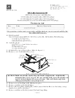
Page 137: ...king from the adhesive gasket and apply the gasket adhesive side to the console around the cutout D Run cable harnesses between Processor and Control Head Label both ends with the Station ID EXAMPLE P...

Page 138: ...dheld requirements and options DIMENSIONS ALWAYS REFER TO THE MANUAL THAT IS SUPPLIED WITH THE CONTROL SYSTEM FOR ANY UNIQUE CONTROL HEAD CONNECTIONS FOR YOUR SYSTEM When cable connections are complet...

Page 139: ......

Page 140: ...Page A 4...

Page 141: ...Select the desired mounting locations and make cutouts per template Refer to the Dimensions Diagram B Check that the two mounting screws will start into the Control Head Remove Control Head from cuto...

Page 142: ...Marine Electronics Dealer for further information on Handheld requirements and options Dual Control Head Connections Terminal Connections Cable Jumper connections 5 and 7 at the Port and Starboard te...

Page 143: ......

Page 144: ...10...

Page 145: ...mmand one 1 Control Head Harness per Con trol Head lever CruiseCommand one 1 Control Head Harness per Control Head lever Included with the Control Head 4 Flat washer Stainless Steel 1 4 inch 4 Screw S...

Page 146: ...over the drain wire at the Control Head is not connected to ground Strip 3 8 9 5mm insulation off each wire Twist the individual strands of the wires to minimize fray ing Crimp a locking fork terminal...

Page 147: ...and Pluggable MS Series ClearCommand Port Lever Starboard Lever Terminal 3 Terminal 3 Red JUMPER Red JUMPER Terminal 5 Blue Terminal 5 JUMPER Terminal 7 JUMPER Terminal 7 Blue PLUGGABLE CONNECTIONS P...

Page 148: ...Page A 18...

Page 149: ...Page A 19 TEMPLATE...

Page 150: ...Page A 20...

Page 151: ...ther Mount To prevent internal condensation and moisture build up the mount is drilled to allow air circulation Part No 12110 400 Series Weather Mount Enclosure Gasket 10241 Control Head Mounting Hole...

Page 152: ...Page A 22...

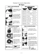
Page 153: ...ceptacle is shown use the same procedure for plug Step 1 Contact Removal Step 4 Contact Insertion Step 2 Wire Stripping 1 Remove wedgelock using needlenose pliers or a hook shaped wire Pull wedge stra...

Page 154: ...Page A 24...

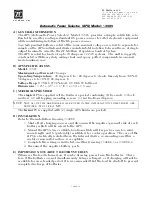
Page 155: ...x 7 9 cm C MATERIALS PROVIDED The single APS is supplied with a hardware packet containing 6 hex nuts 3 lock washers 4 self tapping mounting screws 1 instructions diagram The twin APS is supplied wit...

Page 156: ...Page A 26...

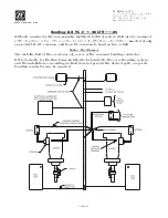
Page 157: ...Page A 27 Drawing 11488D 1 Twin Screw Single APS Connection Alternate Remote Switch...

Page 158: ...Page A 28...

Page 159: ...Page A 29 Drawing 11488D 2 Twin Screw Dual APS Connections...

Page 160: ...Page A 30...

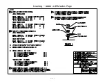
Page 161: ...Page A 31 Drawing 11488D 3 APS Notes Page...

Page 162: ...Page A 32...

Page 163: ...ive terminal of all batteries should be connected at only one point the DC common and from DC common to bond system or hull Metal Hull Vessels The metallic hull of the vessel may also serve as the com...

Page 164: ...Page A 34...

Page 165: ...183 455 Over current and Protection General 46 CFR 111 01 15 b Ambient Temp Machinery Spaces 50 degrees C 46 CFR 111 05 System Grounds 3 Society of Automotive Engineers 400 Commonwealth Drive Warrenda...

Page 166: ...Page A 36...

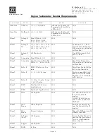
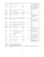
Page 167: ...8902 N A Diesel Cummins B C Series KTA19M3 MTA855 KTA1150M 8912 Most have Magnetic Pickup already installed on flywheel Diesel Detroit DDEC Electronic Sys tem 8902 Must have Detroit data link output m...

Page 168: ...drive adapter needed on 1980 and newer engines Diesel Perkins 4 107 4 108 M 800TI 8902 N A Diesel Perkins 4 154 N A Aetna Part No 8709 Magnetic Sensor must be used in lieu of SAE drive Diesel Perkins...

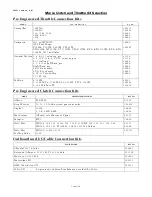
Page 169: ...ont entry 6 8V 71 Front entry 12 16V 149 41736 41736 36680 36680 36680 36680 36680 36680 Perkins 4 236M 6 3544M T6 3544M ST6 3544M SST6 3544M 4 108 W shut off 48931 302026 303878 MAKE TRANSMISSION MOD...

Page 170: ...Page A 40...

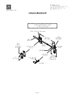
Page 171: ...425 493 1569 MMC 290 Rev 6 01 Universal Mounting Kit 3 16 4 8mm Diameter 7 3 8 187mm 1 4 6 4mm Diameter Selector Lever 2 3 4 70mm Maximum Movement Ball Joint 31126 1 4 28 UNF Stud Jam Nut Shim 31638 C...

Page 172: ...Page A 42...

Page 173: ...Screwdriver Phillips Screwdriver 7 16 Nut Driver or Socket 7 16 Open End Wrench C Actuator Processor Preparation Refer to Figure 1 D Remove cover to Actuator Processor E Remove screws holding Cable Re...

Page 174: ...force 6 Install two screws through the 43C Cable Retainer and into the Actuator Pro cessor 7 Tighten the two screws securely with a Phillips Screwdriver 8 Insert the 43C Cable Connect Nut through the...

Page 175: ...ranty specifically does not provide coverage for 1 Towing or transportation of the vessel or travel to and from the job site or vessel 2 Original installation charges or start up costs 3 Loss of use o...

Page 176: ...Page A 46...

Page 177: ...3 Rev B 1 01 Actuator Processor Serial Serial Number of Remote Stations Purchase Date Dealer s Name Installer s Name Phone Number Purchaser s Name Street Address City State Zip Phone Number YOUR VESSE...

Page 178: ...Page C 48 ZF Mathers LLC 12125 Harbour Reach Drive Suite B Mukilteo WA 98275...

Page 179: ...APPENDIX B...

Page 180: ......

Page 181: ...cal system along with a brief description of their functions B1 1CONTROL SYSTEMS EXAMPLES B1 1 1 9120 Throttle Servo 2 Shift Solenoid Processor and 9122 Throttle Servo 2 Shift Solenoid Troll Solenoid...

Page 182: ...1 2 9121 Basic Single Screw Two Station Diagram The 9210 Processor is designed to pre cisely control speed and direction on vessels equipped with electronic Throttle and mechanical Clutch Selectors Fi...

Page 183: ...w Two Station Diagram The 9221 Processor is designed to precisely control speed direc tion andtrollingvalve on vessels equipped with electronic Throt tle solenoidClutch selection and mechanical Troll...

Page 184: ...ding these limits will not damage the Processor but will render it unusable temporarily The power supply must be capa ble of delivering 10 amperes to each Processor on a continual basis and current su...

Page 185: ...y special attention to the following items DC Power Source Component Location Component Condition Interconnecting Wiring and Harnesses Wire Terminations Plug and Socket Pins Mechanical connections at...

Page 186: ...f the Processor Whenever the factory is called for technical assistance the part number and serial number will be required These numbers pro vide the Service Technician information about the operating...

Page 187: ...fer to Section B5 3 2 page B5 8 The following tone can be produced on all Systems using Sole noid Clutches One Long One Short Tone Refer to Section B5 2 1 page B5 6 E Are there any Error Messages disp...

Page 188: ...tely Items which are sig nificant to you the technician may not seem so to the casual owner or operator An example would bechanges to the engine s fuel system Ask about changes that when initially con...

Page 189: ...tic Power Selector is strongly recommended The APS take inputs from two separate power sources Whichever power source is at the higher voltage level will be automatically switched through C Refer to A...

Page 190: ...mplished through the audible tone emitted at all Remote Sta tions When an audible tone is emitted it will be accompanied by an Error Message at the Processor Also in many cases the Con trol System wil...

Page 191: ...Battery Voltage A Locate the Display LED on the Port or Starboard Processor The Display LED will have the Processor Part Number displayed in a running pattern moving from left to right while the prog...

Page 192: ...y the Tachome ter Sender This signal is utilized in Closed Loop Synchronization or Closed Loop Troll future systems The Control Head s lever position and the resulting outputs of Stations 1 2 3 4 and...

Page 193: ...r Down Scroll Push Button once more returns you to the Applied Battery Voltage Figure B4 9 I The Diagnostic Menu can be exited two ways Do not touch any Push Buttons for 5 minutes The system will auto...

Page 194: ...tage atthe Processor has momentarily dropped below 8 VDC and then returned to a normal operational level This could be due to Loose battery power cable connection Under charged or defective battery Vo...

Page 195: ...tone indicates thatthere is an invalid command signal at the Station in Command The Processor expects a DCvoltage representativeof the Control Head s present lever position This voltage is referred t...

Page 196: ...Figure B5 16 are shown with no Control Heads connected to any Remote Stations When a Control Head is connected the appropriate A D Analog Digital value for the present position of the Control Head s l...

Page 197: ...ontrol Head and the Processor 2 There is an open wire between pin 7 blue wire of a right hand Control Head and the Processor 3 There is an open wire between pin 5 blue wire of a left hand Control Head...

Page 198: ...2 SERVO 1 CONTROL SYSTEM TONES B5 2 1 One Long One Short Tone This tone indicates that the feedback signal which represents the position of the Servo 1 cross bar is out of the expected range This tone...

Page 199: ...one was first encountered The tone will be accompanied by Error Code 62 and is typically caused by one of the following reasons Stiff or frozen selector lever Misadjusted push pull cable Defective pus...

Page 200: ...and plug are not making contact or have a high resistance contact 2 The potentiometer is out of calibration 3 The potentiometer is defective 4 The Control Circuit is defective The Servo 2 feedback si...

Page 201: ...the transfer button and continue to move the Con trol Head lever through the speed range If the tone does notsound until the Control Head lever is close to full throttle Function Code E3 Throttle Maxi...

Page 202: ...the Reference Voltage and sends it back to the Processor The amount of DC voltage which is tapped off is dependant on the position of the Control Head s lever When the lever is fully Astern a small p...

Page 203: ...Counts Command Voltage2 35 VDC501 A D Counts As you can see by the examples even though the Command Volt ages are different between Examples 1 and 2 the resulting A D counts are the same because of th...

Page 204: ...fer Button Depressed for Station 5 A Depress the Up or Down scroll Push Button until four zeroes are displayed without decimal points as shown in Fig ure B6 28 B For Stations 1 4 when the Transfer But...

Page 205: ...as a stuck transfer button the following will happen If Control Head levers are positioned at Neutral Idle a solid tone is heard from all remote stations If Control Head levers are positioned other th...

Page 206: ...le B8 6 Basic Control System Error Codes Error No Title Description 13 Station No 1 Faulted High Station No 1 Control Head s lever position is out of range The input appears to be too high 14 Station...

Page 207: ...Head s Transfer Button has either been closed too long or has been closed since power up 43 CAN Communication Stuffing Error The Control Area Network protocol has detected an error in communication wi...

Page 208: ...d position 63 Servo 1Feedback High Servo one s position feedback voltage is higher than the acceptable range 64 Servo 1 Feedback Low Servo one s position feedback voltage is lower than the acceptable...

Page 209: ...n No 5 Control Head is defective a Replace Station No 5 Control Head b No continuity between pin 5 s of the Control Head Harness connectors b Ensure that the red conductor is properly crimped to pin 5...

Page 210: ...s continuity c No continuity between pin 7 s of the Control Head Harness connectors c Ensure that the blue conductor is properly crimped to pin 7 at both connectors and there is continuity 29 a The St...

Page 211: ...Ensure that the orange conductor is crimped to pin 4 at both ends and the red wire is crimped to pin 5 at both ends of the Harness d The Control Head s Pigtail is miswired d Ensure that the orange co...

Page 212: ...Ensure that the orange conductor is crimped to pin 4 of the connector and connected to pin 4 of the Control Head s terminal block Ensure that the red conductor is crimped to pin 5 of the connector an...

Page 213: ...o 2 with the A0 function c Loss of power to Processor ID No 2 c Restore power to Processor ID No 2 52 a The Serial Harness is not connected at Processor ID No 3 a Connect the Serial Harness into Proce...

Page 214: ...edback potentiometer is out of calibration a Replace the Processor or calibrate the potentiome ter b The Throttle Servo s feedback potentiometer is defective b Replace The Processor or the potentiomet...

Page 215: ...ive b Replace The Processor or the potentiometer c The Processor s Circuit Board is defective c Replace the Processor or the Circuit Board 67 a The Throttle Servo s feedback potentiometer is out of ca...

Page 216: ...ull cable is defective c Replace the Push Pull cable d The Processor s Troll Servo Servo 2 is defective d Replace the Processor e Low battery voltage e Charge repair or replace the battery charging sy...

Page 217: ...ad Cause Remedy a Incorrectly wired Station Harness Cable or Pigtail a Verify that the brown wire is properly con nected to pin 2 on the Control head and pin 2 at the Processor b The Control Head s re...

Page 218: ...with Func tion Code A1 Refer to Section 5 6 1 2 page 5 9 Cause Remedy a The Processor is sensing that the Control Head s lever is moving in the Astern direction Depress the Transfer Button while movi...

Page 219: ...be reversed Cause Remedy a Problem with the Governor a Connect the Break out Box p n 13927 as shown in the Throttle Testing Section of the Service Field Test Unit Manual If variations are seen procee...

Page 220: ...to both Processors d The Port and Starboard Processors have the same ID number d On the Port Processor scroll to Function Code A0 and enter a Value of 01 On the Starboard Processor scroll to Function...

Page 221: ...e wires at pins 5 and 7 at the Control Head Change the Clutch direction with Function Code C5 Table B11 18 Basic Problem Causes and Solutions System Causes Solutions 1 The green LED is lit solid thoug...

Page 222: ...Tach Sender s input frequency If the frequency is varying check the push pull cable for movement If the push pull cable is not moving swap the Port and Starboard Tach Senders If the frequency still v...

Page 223: ...s set to a Value of 01 or 03 b Scroll to Function Code H0 on both Pro cessors and display the frequency of the Tach Signal refer to Section 5 6 5 1 1 page 5 40 If variations of the signal are measured...

Page 224: ...er Switch Wire at the Starter Sole noid Closed contact when In command and at Neutral Table B12 2 Power Start Interlock and Pressure Switch Harness Pin Out PROCESSOR ENGINE and BATTERY Figure B12 2 Po...

Page 225: ...ct that closes when transmission manufacturer s minimum safe operating pressure is reached Pin 10 Red Battery 12 or 24VDC Pin 11 Black Battery DC Return Pin 12 Yellow w Red Trace Starter Switch Wire a...

Page 226: ...3 TO 5 PORT JUMPER PINS 3 TO 7 Table B12 6 Tachometer Sensor Harness Pin Out PROCESSOR TACHOMETER SENSOR Figure B12 8 Tachometer Sensor Harness Pin Out Termination A Conductor Color Termination B Des...

Page 227: ...arness Pin Out PROCESSOR GEAR BOX Figure B12 11 Clutch Troll Harness Pin Out Termination A Conductor Color Termination B Description Pin 3 Red Ahead Clutch Solenoid 24 VDC when Ahead Clutch Selected P...

Page 228: ...ure Switch Ground PB1 Red Pin 10 DC Power PB1 Black Pin 11 DC Power PB2 1 Red Pin 12 Start Interlock Table B13 2 Serial Communication Pigtail Pin Out CIRCUIT BOARD PLUG Figure B13 2 Serial Communicati...

Page 229: ...B11 8 White Pin 10 Troll On Off Table B13 6 Throttle Pigtail Pin Out CIRCUIT BOARD PLUG Figure B13 6 Throttle Pigtail Pin Out Termination A Conductor Color Termination B Description TB8 3 Brown Pin 2...

Page 230: ...12 Current MAN Throttle Harness Pin Out PROCESSOR ENGINE Figure B12 14 Current Throttle Harness Pin Out Termination A Conductor Color Termination B Description Pin 1 Black Engine DC Bus Throttle Signa...

Page 231: ...s of controlling each engine c In addition to the requirements of paragraph a of this section a vessel must have a reliable means for shutting down a propulsion engine at the main pilot house control...

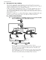
Page 232: ...sure houses an independent Control Processor and requires separate power supplies The system operates on 12 or 24VDC power and can have up to five remote stations depending on the application The syst...

Page 233: ...v Repeat for Starboard side 2 Failure Power failure to ClearCommand 9000 Series A power failure to the ClearCommand 9000 Series circuit board will have the same results as a failed microprocessor a R...

Page 234: ...Appendix B 6...

Page 235: ...f controlling each engine c In addition to the requirements of paragraph a of this section a vessel must have a reliable means for shutting down a propulsion engine at the main pilot house control sta...

Page 236: ...controls offer single lever control of speed and direction Each enclosure houses an independent Control Processor and requires separate power supplies The system operates on 12 or 24VDC power and can...

Page 237: ...k to Neutral Reconnect the green wire v Repeat for Starboard side 2 Failure Power failure to ClearCommand 9000 Series A power failure to the ClearCommand 9000 Series circuit board will have the same r...

Page 238: ...Appendix B 10...

Page 239: ...controlling each engine c In addition to the requirements of paragraph a of this section a vessel must have a reliable means for shutting down a propulsion engine at the main pilot house control stat...

Page 240: ...arine engine controls offer single lever control of speed and direction Each enclosure houses an independent Control Processor and requires separate power supplies The system operates on 12 or 24VDC p...

Page 241: ...tral Reconnect the green wire v Repeat for Starboard side 2 Failure Power failure to ClearCommand 9000 Series A power failure to the ClearCommand 9000 Series circuit board will have the same results a...

Page 242: ...Appendix B 14...

Page 243: ...do Brazil S A T 5515 235 2301 Avenida Conda Zepplin 1935 F 5515 235 2233 CEP 18103 0000 Sorocaba Brazil richard bergamini zf com www zf marine com CHILI Christian Rogers Nickelmann Equipamiento Marin...

Page 244: ...ny pein piening propeller de www piening propeller de GREECE 2386 Demetris Kyriazis Amaltheia Marine Ltd T 30210 25 88 985 13 Papaflessa Str F 30210 25 89 986 143 43 N Halkidona Athens Greece amalmar...

Page 245: ...F 44 115 986 9261 Nottingham United Kingdom NG7 2SX England adilicense zf com www zf marine com SINGAPORE 157 Steven Wee Mammoth Enterprises Pte Ltd mail PO Box 283 T 65 6 44 88266 Siglap Post Office...

Page 246: ...dle East LLC T 971 6 574074 mail PO Box 26093 F 971 6 5747174 Sharjah U A E shipping 502 Golden Tower Building Sharjah narsimhan manian zf marine com thiru moorthy zf marine com www zf marine com UNIT...

Page 247: ...Service Field Test Unit Reference Manual MM13927 Rev E 4 07...

Page 248: ......

Page 249: ...Pulse Width Modulation with Duty Cycle Meter D 3 Frequency Hz D 3 Procedure Clutch Testing D 4 Neutral Solenoid Testing D 4 Ahead Solenoid Testing D 4 Astern Solenoid Testing D 4 Procedures Troll Tes...

Page 250: ...Page ii Table of Contents...

Page 251: ...ies ClearCommand Processor FIGURE D 2 CRUISECOMMAND CONNECTOR LOCATIONS FIGURE D 3 EXAMPLE OF CLEARCOMMAND PIGTAIL LOCATIONS Rev Date Revision Description A 11 02 Revised Section 1 0 Table 1 B 2 03 Re...

Page 252: ...t mA A Ensure power is removed from both the Engine Electronics and the Processor B Disconnect the Throttle Harness from the number 1 Processor connector pigtail C Insert the Break out Box between the...

Page 253: ...Only Mode I The measurement should be 91 93 of the voltage measured in step F e g Idle 8 of 12 VDC reference or 0 96 VDC Full Throttle 92 of 12 VDC reference or 11 04 VDC PWM Pulse Width Modulation wi...

Page 254: ...moved from both the Processor and the Clutch Power Supply B Disconnect the Clutch Harness from the number 3 Processor connector pigtail C Insert the Break out Box between the number 3 Processor connec...

Page 255: ...the red LED on the Control Head becomes lit solid Troll Command Proportional Solenoid Testing with Amp Meter A Ensure power is removed from both the Processor and the Clutch Power Supply B Disconnect...

Page 256: ...Engaged A Leave the Break out Box and Multimeter in the same position as left in 2nd Gear Disengaged B Start the engine s C Depress the Transfer Button while moving the lever s into the Ahead detent...

Page 257: ...socket labeled and the red lead into the socket labeled FREQ E Turn power On to the Processor and take command at any Remote Station F The appropriate Idle Frequency for the application should be mea...

Page 258: ...er in the Neutral Idle position E The measurementon the Neutral TestPointshouldbe12 or 24 VDC depending on the Solenoid s rating and the LED adja cent to the socket should be illuminated F Move the Co...

Page 259: ...ld be 0 VDC and the adjacent LED should not be lit G Position the Control Head lever into the Ahead detent The measurement should be 12 or 24 VDC depending on the Ahead Solenoid s rating The LED adjac...

Page 260: ...any Remote Station with the Control Head lever in the Neutral Idle position F The measurement should be 0 VDC and the adjacent LED should not be lit G Position the Control Head lever into the Astern...

Page 261: ...s shown in Figure 2 12 E Turn power On to the Processor and the Clutch Power Sup ply and take command at a Remote Station with the Control Head lever in the Neutral Idle position F Depress the Transfe...

Page 262: ...pproximately 2 sec onds until the red LED on the Control Head begins blinking at a fast rate Troll Mode Indication G Flip switch away from Troll Command to read current through meter H Move the Contro...

Page 263: ...ICE FIELD TEST UNIT MM13927 RvD 10 03 Page 3 1 3 PARTS LIST Table 3 2 Parts List Part Name ZF Mathers Part No Service Field Test Unit 13927 Technical Manual MM13927 Multimeter Test Control Head Dual 1...

Page 264: ...SERVICE FIELD TEST UNIT MM13927 RvD 10 03 Page 3 2...

Page 265: ...APPENDIX C...

Page 266: ......

Page 267: ...Appendix C 1 Drawing 12284A 1 ClearCommand Diagram all options...

Page 268: ...Appendix C 2...

Page 269: ...Appendix C 3 Drawing 12284A 2 ClearCommand Circuit Board Connections...

Page 270: ...Appendix C 4...

Page 271: ...Appendix C 5 Drawing 12284A 3 ClearCommand Drawing Notes Page...

Page 272: ...Appendix C 6...

Reviews: