TROUBLESHOOTING
PageB2-1
B2 TROUBLESHOOTING QUESTIONS
Prior to lifting a tool or stepping on board the vessel,
many problems can be resolved by asking the customer
the following basic questions:
A) Is the System installed on a Single, Twin or Mul-
tiple Screw vessel?
• If the System is installed on a Single Screw vessel, this
question does not have much value in narrowing down the
source of the problem.
• If the System is installed on a Twin or more Screw applica-
tion, this question is quite useful, if you ask the following
question.
1. Does the problem or symptom occur on the Port, Starboard
or both sides?
•
If the problem or symptom occurs on one side only, you have
effectively eliminated 50% of the possible causes. For exam-
ple, the symptom only occurs on the Port side. All of the com-
ponents on the Starboard side have been eliminated as
potential causes.
B) What is the Part Number and Serial Number of
the Processor?
Whenever the factory is called for technical assistance, the part
number and serial number will be required. These numbers pro-
vide the Service Technician information about the operating
characteristics of the Processor. The numbers are located on the
Processor’s front cover.
C) How many Remote Stations are there?
• If only one Remote Station is present, not much will be gained
by asking this question. However, if more than one Remote
Station is being used, command should be taken from one of
the other Stations to see if the problem occurs from another
Station.
• If the problem occurs from more than one Remote Station, the
odds are that the Control Heads are not the cause of the trou-
ble.
• If the problem occurs at one Remote Station only, there is a
greater chance of the Control Head or the Control Head Har-
ness of being the cause.
D) Are any tones generated when the problem
occurs?
The tones are used to bring the operator’s attention to a possible
condition or problem.
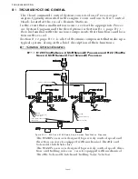
The following basic tones can be produced on all Systems:
Slow Repetitive Tone
(Refer to Section B5-1.1, page B5-1)
Summary of Contents for ClearCommand 9000 Series
Page 132: ......
Page 133: ...APPENDIX A...
Page 134: ......
Page 139: ......
Page 140: ...Page A 4...
Page 143: ......
Page 144: ...10...
Page 148: ...Page A 18...
Page 149: ...Page A 19 TEMPLATE...
Page 150: ...Page A 20...
Page 152: ...Page A 22...
Page 154: ...Page A 24...
Page 156: ...Page A 26...
Page 157: ...Page A 27 Drawing 11488D 1 Twin Screw Single APS Connection Alternate Remote Switch...
Page 158: ...Page A 28...
Page 159: ...Page A 29 Drawing 11488D 2 Twin Screw Dual APS Connections...
Page 160: ...Page A 30...
Page 161: ...Page A 31 Drawing 11488D 3 APS Notes Page...
Page 162: ...Page A 32...
Page 164: ...Page A 34...
Page 166: ...Page A 36...
Page 170: ...Page A 40...
Page 172: ...Page A 42...
Page 176: ...Page A 46...
Page 178: ...Page C 48 ZF Mathers LLC 12125 Harbour Reach Drive Suite B Mukilteo WA 98275...
Page 179: ...APPENDIX B...
Page 180: ......
Page 234: ...Appendix B 6...
Page 238: ...Appendix B 10...
Page 242: ...Appendix B 14...
Page 247: ...Service Field Test Unit Reference Manual MM13927 Rev E 4 07...
Page 248: ......
Page 250: ...Page ii Table of Contents...
Page 264: ...SERVICE FIELD TEST UNIT MM13927 RvD 10 03 Page 3 2...
Page 265: ...APPENDIX C...
Page 266: ......
Page 267: ...Appendix C 1 Drawing 12284A 1 ClearCommand Diagram all options...
Page 268: ...Appendix C 2...
Page 269: ...Appendix C 3 Drawing 12284A 2 ClearCommand Circuit Board Connections...
Page 270: ...Appendix C 4...
Page 271: ...Appendix C 5 Drawing 12284A 3 ClearCommand Drawing Notes Page...
Page 272: ...Appendix C 6...


