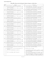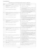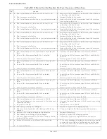
TROUBLESHOOTING
PageB5-8
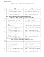
• Defective push-pull cable.
• Low battery voltage.
• Defective Processor.
In order to isolate the cause to one of these five items, follow the
steps below:
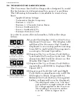
A) Turn the power ON to the Processor.
• If the tone is not present continue with step C)
• If the tone is present, check the DC voltage to the Processor by
accessing the Diagnostic Menu
H0
. If the voltage is adequate
continue with step B.
B) Disconnect the push-pull cable from the selector lever.
• If the tone is still present after cycling power, replace the Pro-
cessor.
• If the tone is no longer present, continue with step C)
C) If disconnected, reconnect the push-pull cable.
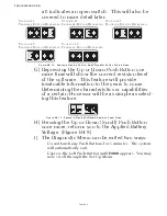
D) Depress the Transfer Button while moving the Control
Head lever to the Ahead detent.
E) Release the transfer button and continue to move the Con-
trol Head lever through the speed range.
• If the tone does not sound until the Control Head lever is close
to full throttle, Function Code
E3
Throttle Maximum is misad-
justed.
• If the tone sounds earlier than full throttle, continue with step
F).
F) Disconnect the push-pull cable from the selector lever.
G) Manually reposition the selector lever (Idle to Full).
• If the selector lever is very stiff it needs to be serviced.
• If the selector lever moves freely, the push-pull cable is defec-
tive and needs replacing.
B5-4 C
LUTCH
S
OLENOID
C
ONTROL
S
YSTEM
T
ONES
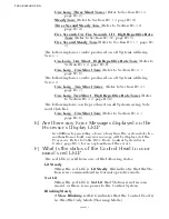
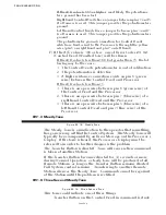
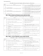
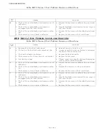
B5-4.1 One Long - One Short Tone
This tone can be produced if solenoid monitoring is turned ON
with Function Code
H2
.
When this tone is sounded this tone will also be accompanied by
one of the following error codes:
1
- Clutch Astern Shorted
2
- Clutch Astern Open
5
- Clutch Ahead Shorted
6
- Clutch Ahead Open
Figure B5-27: One Long - One Short Tone
Summary of Contents for ClearCommand 9000 Series
Page 132: ......
Page 133: ...APPENDIX A...
Page 134: ......
Page 139: ......
Page 140: ...Page A 4...
Page 143: ......
Page 144: ...10...
Page 148: ...Page A 18...
Page 149: ...Page A 19 TEMPLATE...
Page 150: ...Page A 20...
Page 152: ...Page A 22...
Page 154: ...Page A 24...
Page 156: ...Page A 26...
Page 157: ...Page A 27 Drawing 11488D 1 Twin Screw Single APS Connection Alternate Remote Switch...
Page 158: ...Page A 28...
Page 159: ...Page A 29 Drawing 11488D 2 Twin Screw Dual APS Connections...
Page 160: ...Page A 30...
Page 161: ...Page A 31 Drawing 11488D 3 APS Notes Page...
Page 162: ...Page A 32...
Page 164: ...Page A 34...
Page 166: ...Page A 36...
Page 170: ...Page A 40...
Page 172: ...Page A 42...
Page 176: ...Page A 46...
Page 178: ...Page C 48 ZF Mathers LLC 12125 Harbour Reach Drive Suite B Mukilteo WA 98275...
Page 179: ...APPENDIX B...
Page 180: ......
Page 234: ...Appendix B 6...
Page 238: ...Appendix B 10...
Page 242: ...Appendix B 14...
Page 247: ...Service Field Test Unit Reference Manual MM13927 Rev E 4 07...
Page 248: ......
Page 250: ...Page ii Table of Contents...
Page 264: ...SERVICE FIELD TEST UNIT MM13927 RvD 10 03 Page 3 2...
Page 265: ...APPENDIX C...
Page 266: ......
Page 267: ...Appendix C 1 Drawing 12284A 1 ClearCommand Diagram all options...
Page 268: ...Appendix C 2...
Page 269: ...Appendix C 3 Drawing 12284A 2 ClearCommand Circuit Board Connections...
Page 270: ...Appendix C 4...
Page 271: ...Appendix C 5 Drawing 12284A 3 ClearCommand Drawing Notes Page...
Page 272: ...Appendix C 6...

