TROUBLESHOOTING
Page B7-1
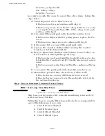
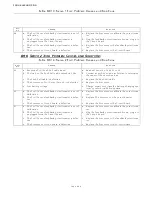
B7 TROUBLESHOOTING STUCK TRANSFER BUTTON
The Transfer Button is a normally open, momentary
switch. The only time the switch should close is when it
is depressed to take command or when entering or
departing various other functions. In the event that the
Transfer Button became stuck in the closed position, the
following will occur:
• The Transfer Button would have to be closed for 15 sec-
onds or more.
• The throttle and clutch are not affected.
• A solid tone is heard from all remote stations, until the
button’s contact opens or transfer to another remote sta-
tion has taken place.
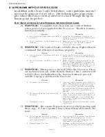
If a Control Head that is not in command has a stuck
transfer button, the following will happen:
• If Control Head levers are positioned at Neutral/Idle, a
solid tone is heard from all remote stations.
• If Control Head levers are positioned other than Neutral/
Idle, a three (3) second tone is heard from all remote sta-
tions.
• Error Code
33
-
42
, depending on which remote station,
will be shown on the Processor Display.
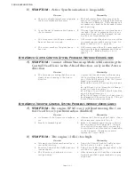
• Command can be taken at any other operational remote
station.
• After one (1) second command can be regained at the
remote station with the stuck button as long as the prob-
lem has been corrected by depressing the transfer button.
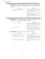
If a stuck Transfer Button is suspected, this can be veri-
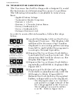
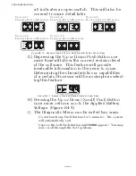
fied by looking at the Station Select status (
1
or
0
) as out-
lined in Section B6-3,
• An Error Code
33
-
42
will be shown on the Display,
depending on which Station is experiencing the problem.
Summary of Contents for ClearCommand 9000 Series
Page 132: ......
Page 133: ...APPENDIX A...
Page 134: ......
Page 139: ......
Page 140: ...Page A 4...
Page 143: ......
Page 144: ...10...
Page 148: ...Page A 18...
Page 149: ...Page A 19 TEMPLATE...
Page 150: ...Page A 20...
Page 152: ...Page A 22...
Page 154: ...Page A 24...
Page 156: ...Page A 26...
Page 157: ...Page A 27 Drawing 11488D 1 Twin Screw Single APS Connection Alternate Remote Switch...
Page 158: ...Page A 28...
Page 159: ...Page A 29 Drawing 11488D 2 Twin Screw Dual APS Connections...
Page 160: ...Page A 30...
Page 161: ...Page A 31 Drawing 11488D 3 APS Notes Page...
Page 162: ...Page A 32...
Page 164: ...Page A 34...
Page 166: ...Page A 36...
Page 170: ...Page A 40...
Page 172: ...Page A 42...
Page 176: ...Page A 46...
Page 178: ...Page C 48 ZF Mathers LLC 12125 Harbour Reach Drive Suite B Mukilteo WA 98275...
Page 179: ...APPENDIX B...
Page 180: ......
Page 234: ...Appendix B 6...
Page 238: ...Appendix B 10...
Page 242: ...Appendix B 14...
Page 247: ...Service Field Test Unit Reference Manual MM13927 Rev E 4 07...
Page 248: ......
Page 250: ...Page ii Table of Contents...
Page 264: ...SERVICE FIELD TEST UNIT MM13927 RvD 10 03 Page 3 2...
Page 265: ...APPENDIX C...
Page 266: ......
Page 267: ...Appendix C 1 Drawing 12284A 1 ClearCommand Diagram all options...
Page 268: ...Appendix C 2...
Page 269: ...Appendix C 3 Drawing 12284A 2 ClearCommand Circuit Board Connections...
Page 270: ...Appendix C 4...
Page 271: ...Appendix C 5 Drawing 12284A 3 ClearCommand Drawing Notes Page...
Page 272: ...Appendix C 6...

