INTRODUCTION
Page 1-3
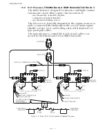
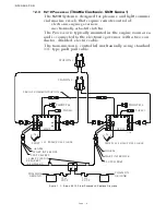
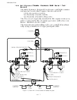
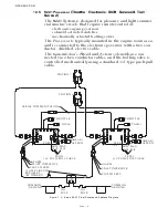
1-2.2 9121 Processor
(Throttle-Servo 2, Shift-Solenoid, Troll-Servo 1)
The
9121
System is designed for pleasure and light commer-
cial marine vessels that require remote control of:
• mechanically actuated engines
• solenoid activated clutches
• mechanical trolling valves.
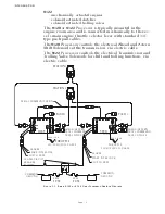
The Processor is typically mounted in the engine room area
and is connected mechanically to the vessel’s main engine
throttle selector lever and trolling valve with standard 33C
type push-pull cables.
The transmission is controlled via electrical cables con-
nected to the Ahead and Astern Shift Solenoids.
Figure 1-2: Basic 9121 ClearCommand System Diagram
IDLE
FULL
33C PUSH/PULL CABLE
33C PUSH/PULL CABLE
IDLE
FULL
THROTTLE
TROLL
THROTTLE
TROLL
STBD
STATION 2
STATION 1
PORT
12295A
SERIAL COMMUNICATION
10 AMP CIRCUIT
BREAKERS
(BY OTHERS)
APS
CLUTCH PRES.
START INTERLOCK
ALARM
START INTERLOCK
CLUTCH PRES.
ALARM
TACH 1
TACH 1
MAX
SLIP
MIN
SLIP
MAX
SLIP
MIN
SLIP
AHEAD/
ASTERN
AHEAD/
ASTERN
30A
FUSE
-
+
-
+
GROUND
COMMON
GROUND
COMMON
30A
FUSE
Summary of Contents for ClearCommand 9000 Series
Page 132: ......
Page 133: ...APPENDIX A...
Page 134: ......
Page 139: ......
Page 140: ...Page A 4...
Page 143: ......
Page 144: ...10...
Page 148: ...Page A 18...
Page 149: ...Page A 19 TEMPLATE...
Page 150: ...Page A 20...
Page 152: ...Page A 22...
Page 154: ...Page A 24...
Page 156: ...Page A 26...
Page 157: ...Page A 27 Drawing 11488D 1 Twin Screw Single APS Connection Alternate Remote Switch...
Page 158: ...Page A 28...
Page 159: ...Page A 29 Drawing 11488D 2 Twin Screw Dual APS Connections...
Page 160: ...Page A 30...
Page 161: ...Page A 31 Drawing 11488D 3 APS Notes Page...
Page 162: ...Page A 32...
Page 164: ...Page A 34...
Page 166: ...Page A 36...
Page 170: ...Page A 40...
Page 172: ...Page A 42...
Page 176: ...Page A 46...
Page 178: ...Page C 48 ZF Mathers LLC 12125 Harbour Reach Drive Suite B Mukilteo WA 98275...
Page 179: ...APPENDIX B...
Page 180: ......
Page 234: ...Appendix B 6...
Page 238: ...Appendix B 10...
Page 242: ...Appendix B 14...
Page 247: ...Service Field Test Unit Reference Manual MM13927 Rev E 4 07...
Page 248: ......
Page 250: ...Page ii Table of Contents...
Page 264: ...SERVICE FIELD TEST UNIT MM13927 RvD 10 03 Page 3 2...
Page 265: ...APPENDIX C...
Page 266: ......
Page 267: ...Appendix C 1 Drawing 12284A 1 ClearCommand Diagram all options...
Page 268: ...Appendix C 2...
Page 269: ...Appendix C 3 Drawing 12284A 2 ClearCommand Circuit Board Connections...
Page 270: ...Appendix C 4...
Page 271: ...Appendix C 5 Drawing 12284A 3 ClearCommand Drawing Notes Page...
Page 272: ...Appendix C 6...


