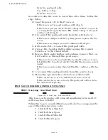
TROUBLESHOOTING
Page B9-6
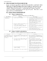
B9-2 S
ERVO
2 T
HROTTLE
P
ROBLEM
C
AUSES
AND
S
OLUTIONS
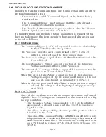
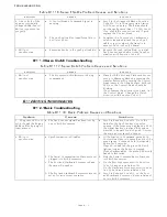
B9-3 S
ERVO
1 C
LUTCH
P
ROBLEM
C
AUSES
AND
S
OLUTIONS
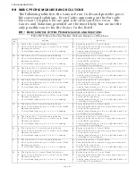
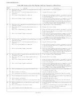
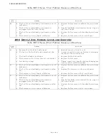
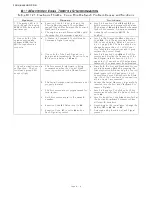
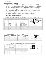
Error
No.
Causes
Solutions
59 a. External Interference, such as a lightning strike.
a. If the error message is displayed once and you are able
to clear the error, take no further actions at this time.
If the error cannot be cleared, replace the Processor.
b. Component failure.
b. Replace the Processor.
60 a. External Interference, such as a lightning strike.
a. If the error message is displayed once and you are able
to clear the error, take no further actions at this time.
If the error cannot be cleared, replace the Processor.
b. Component failure.
b. Replace the Processor.
61 a. External Interference, such as a lightning strike.
a. If the error message is displayed once and you are able
to clear the error, take no further actions at this time.
If the error cannot be cleared, replace the Processor.
b. Component failure.
b. Replace the Processor.
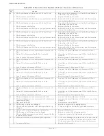
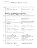
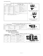
Table B9-10: Servo 2 Throttle Problem Causes and Solutions
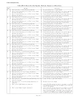
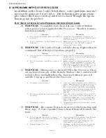
Error
No.
Causes
Solutions
65
a. Excessive Throttle Push-Pull cable travel.
a. Readjust Function Code E2 or E3.
b. The load on the Push-Pull cable exceeds 40 Lbs.
b. Contact a certified engine technician to determine
the cause of the excessive load.
c. The Push-Pull cable is defective.
c. Replace the Push-Pull cable.
d. The Processor’s Throttle Servo (Servo 2) is defec-
tive.
d. Replace the Processor.
e. Low battery voltage.
e. Charge, repair or replace the battery, charging sys-
tem or power distribution system.
66
a. The Throttle Servo’s feedback potentiometer is out
of calibration.
a. Replace the Processor or calibrate the potentiome-
ter.
b. The Throttle Servo’s feedback potentiometer is
defective.
b. Replace The Processor or the potentiometer.
c. The Processor’s Circuit Board is defective.
c. Replace the Processor or the Circuit Board
67
a. The Throttle Servo’s feedback potentiometer is out
of calibration.
a. Replace the Processor or calibrate the potentiome-
ter.
b. The Throttle Servo’s feedback potentiometer is
unplugged from the Circuit Board.
b. Plug the feedback potentiometer’s brown plug into
the Circuit Board.
c. The Throttle Servo’s feedback potentiometer is
defective.
c. Replace the Processor or the feedback potentiome-
ter.
d. The Processor’s Circuit Board is defective.
d. Replace the Processor or the Circuit Board.
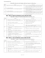
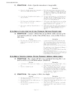
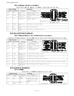
Table B9-11: Servo 1 Clutch Problem Causes and Solutions
Error
No.
Causes
Solutions
62
a. Excessive Clutch Push-Pull cable travel.
a. Readjust Function Code C6 and or C7.
b. The load on the Push-Pull cable exceeds 40 Lbs.
b. Contact a certified Marine Transmission techni-
cian to determine the cause of the excessive load.
c. The Push-Pull cable is defective.
c. Replace the Push-Pull cable.
d. The Processor’s Clutch Servo (Servo 1) is defective. d. Replace the Processor.
e. Low battery voltage.
e. Charge, repair or replace the battery, charging sys-
tem or power distribution system.
63
a. The Clutch Servo’s feedback potentiometer is out of
calibration.
a. Replace the Processor or calibrate the potentiome-
ter.
b. The Clutch Servo’s feedback potentiometer is defec-
tive.
b. Replace the Processor or replace the potentiome-
ter.
c. The Processor’s Circuit Board is defective.
c. Replace the Processor or the Circuit Board.
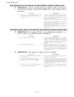
Table B9-9: Basic Control System Problem Causes and Solutions
Summary of Contents for ClearCommand 9000 Series
Page 132: ......
Page 133: ...APPENDIX A...
Page 134: ......
Page 139: ......
Page 140: ...Page A 4...
Page 143: ......
Page 144: ...10...
Page 148: ...Page A 18...
Page 149: ...Page A 19 TEMPLATE...
Page 150: ...Page A 20...
Page 152: ...Page A 22...
Page 154: ...Page A 24...
Page 156: ...Page A 26...
Page 157: ...Page A 27 Drawing 11488D 1 Twin Screw Single APS Connection Alternate Remote Switch...
Page 158: ...Page A 28...
Page 159: ...Page A 29 Drawing 11488D 2 Twin Screw Dual APS Connections...
Page 160: ...Page A 30...
Page 161: ...Page A 31 Drawing 11488D 3 APS Notes Page...
Page 162: ...Page A 32...
Page 164: ...Page A 34...
Page 166: ...Page A 36...
Page 170: ...Page A 40...
Page 172: ...Page A 42...
Page 176: ...Page A 46...
Page 178: ...Page C 48 ZF Mathers LLC 12125 Harbour Reach Drive Suite B Mukilteo WA 98275...
Page 179: ...APPENDIX B...
Page 180: ......
Page 234: ...Appendix B 6...
Page 238: ...Appendix B 10...
Page 242: ...Appendix B 14...
Page 247: ...Service Field Test Unit Reference Manual MM13927 Rev E 4 07...
Page 248: ......
Page 250: ...Page ii Table of Contents...
Page 264: ...SERVICE FIELD TEST UNIT MM13927 RvD 10 03 Page 3 2...
Page 265: ...APPENDIX C...
Page 266: ......
Page 267: ...Appendix C 1 Drawing 12284A 1 ClearCommand Diagram all options...
Page 268: ...Appendix C 2...
Page 269: ...Appendix C 3 Drawing 12284A 2 ClearCommand Circuit Board Connections...
Page 270: ...Appendix C 4...
Page 271: ...Appendix C 5 Drawing 12284A 3 ClearCommand Drawing Notes Page...
Page 272: ...Appendix C 6...


