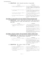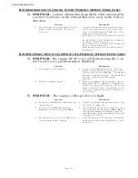
TROUBLESHOOTING
Page B11-1
B11 SYNCHRONIZATION TROUBLESHOOTING
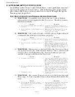
If you encounter a problem with Synchronization, it will more than
likely one of the following; failure to attempt to synchronize, syn-
chronizing at different RPM’s or RPM variations of one or both
engines while synchronized. Each problem is distinct and the
cause may differ depending on the type of Synch. Therefore, each
type is discussed individually.
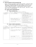
B11-1E
QUAL
T
HROTTLE
S
YNCHRONIZATION
B11-1.1Basic Troubleshooting
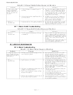
B11-1.2Servo Throttle Troubleshooting
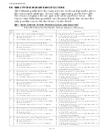
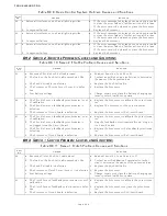
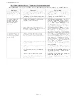
Table B11-15: Basic Problem Causes and Solutions
Symptom
Causes
Solutions
1. Will not
synchronize.
a. Synchronization is Disabled
a. At the Station-in-Command, move both
Control Head levers to more than 5% of
the speed range. Press and hold the trans-
fer button for 5 seconds.
If synch is disabled, the green LED will
light as long as the button is pressed.
If synch was enabled, the green LED
would have blinked twice.
b. The Serial Communication Harness is not
plugged into both Processors.
b. Plug the Serial Communication Harness
into both Processors.
c. The Port and Starboard Processors are
not set up for Twin Screw operation.
c. Scroll to Function Code A1, on the Port
and Starboard Processor. Enter a Value of
02 into both Processors.
d. The Port and Starboard Processors have
the same ID number.
d. On the Port Processor, scroll to Function
Code A0 and enter a Value of 01.
On the Starboard Processor, scroll to
Function Code A0 and enter a Value of 02.
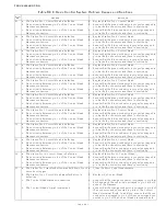
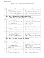
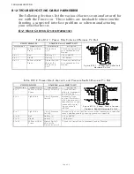
Table B11-16: Servo Throttle Problem Causes and Solutions
Symptom
Causes
Solutions
1. The green LED is lit
solid, though the Engine
RPM’s differ by a signifi-
cant amount.
a. The throttle travel from Idle to Full is set
differently on the Port and Starboard Pro-
cessors.
a. Scroll to Function Codes E2 and E3 on
both Processors and compare the Values.
The Values of E2 and E3 must be the same
for both Processors.
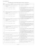
b. The engines run at different RPM’s with
equal travel of the Governors’/ Carbure-
tors’ selector lever.
b. While underway at cruising speed,
decrease the Value of Function Code E3
on the Processor running at the higher
RPM until both engine are at the same
RPM.
This is not a normal condition and is
masking the actual problem with the
engine. Top speed may be sacrificed by
doing so.
Install Tach Senders and enable Active
Synchronization with Function Code E7.
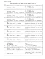
c. Excessive back-lash in the push-pull
cable(s) or linkage.
c. Remove the excessive back-lash or install
Tach Senders and enable Active Synchro-
nization with Function Code E7.
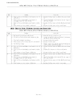
d. Excessive bends in the push-pull cable(s). d. Reroute the push-pull cable(s) or install
Tach Sender and enable Active Synchro-
nization with Function Code E7.
Summary of Contents for ClearCommand 9000 Series
Page 132: ......
Page 133: ...APPENDIX A...
Page 134: ......
Page 139: ......
Page 140: ...Page A 4...
Page 143: ......
Page 144: ...10...
Page 148: ...Page A 18...
Page 149: ...Page A 19 TEMPLATE...
Page 150: ...Page A 20...
Page 152: ...Page A 22...
Page 154: ...Page A 24...
Page 156: ...Page A 26...
Page 157: ...Page A 27 Drawing 11488D 1 Twin Screw Single APS Connection Alternate Remote Switch...
Page 158: ...Page A 28...
Page 159: ...Page A 29 Drawing 11488D 2 Twin Screw Dual APS Connections...
Page 160: ...Page A 30...
Page 161: ...Page A 31 Drawing 11488D 3 APS Notes Page...
Page 162: ...Page A 32...
Page 164: ...Page A 34...
Page 166: ...Page A 36...
Page 170: ...Page A 40...
Page 172: ...Page A 42...
Page 176: ...Page A 46...
Page 178: ...Page C 48 ZF Mathers LLC 12125 Harbour Reach Drive Suite B Mukilteo WA 98275...
Page 179: ...APPENDIX B...
Page 180: ......
Page 234: ...Appendix B 6...
Page 238: ...Appendix B 10...
Page 242: ...Appendix B 14...
Page 247: ...Service Field Test Unit Reference Manual MM13927 Rev E 4 07...
Page 248: ......
Page 250: ...Page ii Table of Contents...
Page 264: ...SERVICE FIELD TEST UNIT MM13927 RvD 10 03 Page 3 2...
Page 265: ...APPENDIX C...
Page 266: ......
Page 267: ...Appendix C 1 Drawing 12284A 1 ClearCommand Diagram all options...
Page 268: ...Appendix C 2...
Page 269: ...Appendix C 3 Drawing 12284A 2 ClearCommand Circuit Board Connections...
Page 270: ...Appendix C 4...
Page 271: ...Appendix C 5 Drawing 12284A 3 ClearCommand Drawing Notes Page...
Page 272: ...Appendix C 6...


