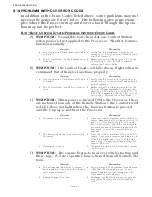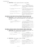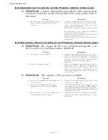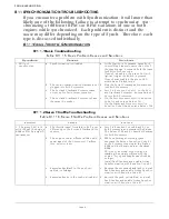
TROUBLESHOOTING
PageB12-4
B12-2.2Ahead, Neutral, and Astern
B12-3C
LUTCH
/T
ROLL
H
ARNESSES
B12-3.1Ahead, Astern, Troll On/Off & Troll Command
B12-4T
HROTTLE
H
ARNESSES
B12-4.1PWM
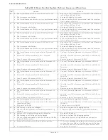
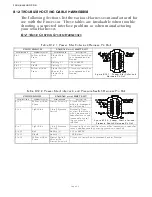
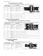
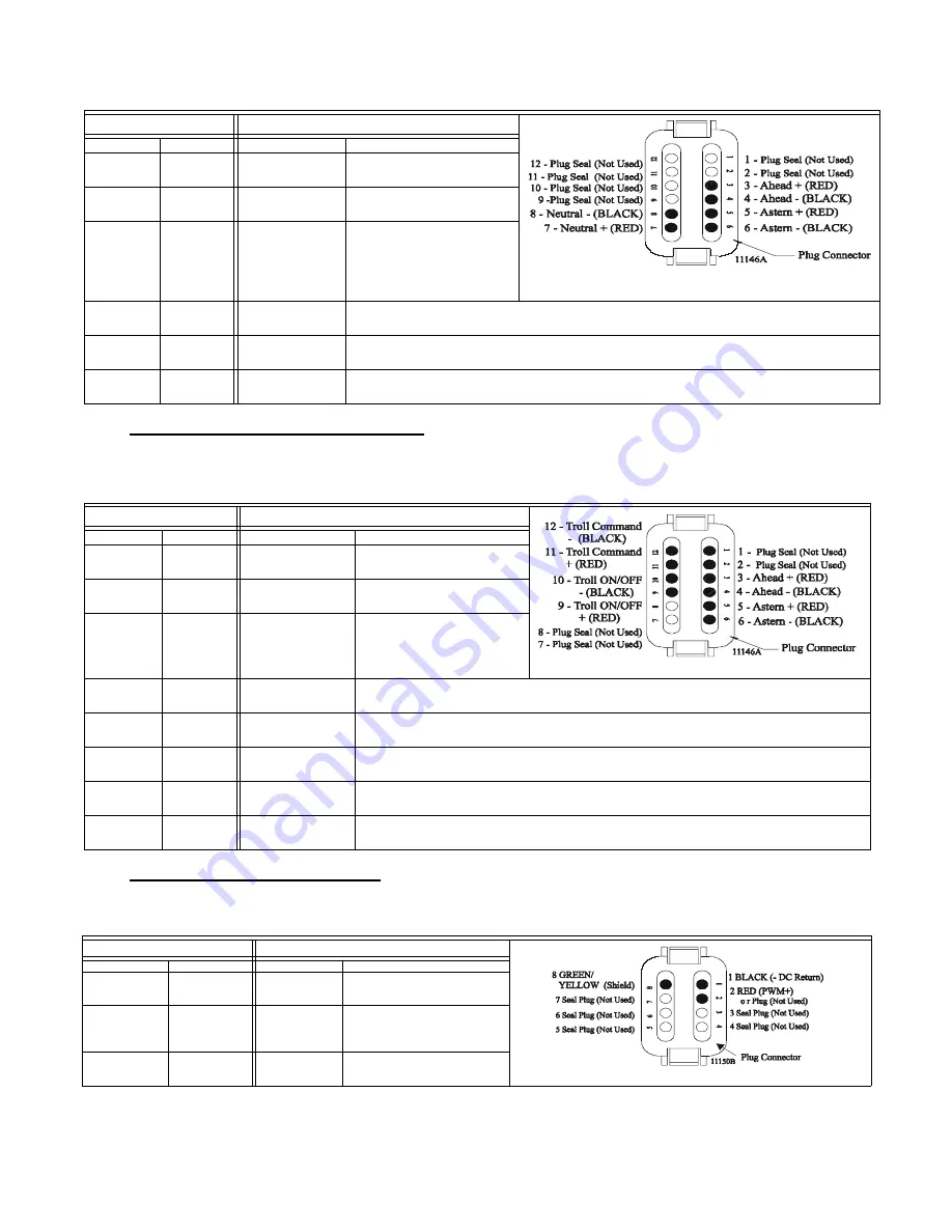
Table B12-8: Ahead, Neutral, and Astern Clutch Harness Pin-Out
PROCESSOR
GEAR BOX
Figure B12-10: Clutch, Ahead, Astern, and Neutral
Harness Pin Out
Termination A
Conductor Color
Termination B
Description
Pin 3
Red
Ahead Sole-
noid
+24 VDC when Ahead
Clutch Selected
Pin 4
Black
Ahead Clutch
Solenoid
-VDC Return for Ahead
Clutch
Pin 5
Red
Astern Clutch
Solenoid
+24 VDC when Astern
Clutch Selected
Pin 6
Black
Astern Sole-
noid
-VDC Return for Astern Clutch
Pin 7
Red
Neutral Sole-
noid
+24 VDC at all times
Pin 8
Black
Neutral Sole-
noid
-VDC Return for Neutral Solenoid
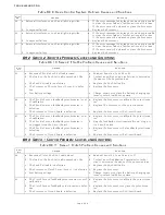
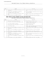
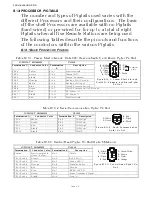
Table B12-9: Ahead, Astern, Troll On/Off and Troll Command Clutch/Troll Harness Pin-Out
PROCESSOR
GEAR BOX
Figure B12-11: Clutch/Troll Harness Pin Out
Termination A
Conductor Color
Termination B
Description
Pin 3
Red
Ahead Clutch
Solenoid
+24 VDC when Ahead
Clutch Selected
Pin 4
Black
Ahead Clutch
Solenoid
-VDC Return for Ahead
Clutch
Pin 5
Red
Astern Clutch
Solenoid
+24 VDC when Astern
Clutch Selected
Pin 6
Black
Astern Clutch
Solenoid
-VDC Return for Astern Clutch
Pin 9
Red
Troll On/Off
Solenoid
+24 VDC when Troll is selected.
Pin 10
Black
Troll On/Off
Solenoid
-VDC Return for Troll On/Off Solenoid
Pin 11
Red
Troll Command
Solenoid
0- 100% Duty Cycle @ 500Hz. for Controlling Proportional Solenoid Valve
Pin 12
Black
Troll Command
Solenoid
-VDC Return for Troll Command Solenoid
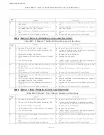
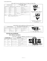
Table B12-10: PWM Throttle Harness Pin-Out
PROCESSOR
ENGINE
Figure B12-12: PWM Throttle Harness Pin Out
Termination A
Conductor Color
Termination B
Description
Pin 1
Black
Engine DC-
Bus
Throttle Signal Return
Pin 2
Red
ECM
PWM Throttle Signal- 0-
100% Duty Cycle @
500Hz.
Pin 8
Green/ Yel-
low
N/C
N/A
Summary of Contents for ClearCommand 9000 Series
Page 132: ......
Page 133: ...APPENDIX A...
Page 134: ......
Page 139: ......
Page 140: ...Page A 4...
Page 143: ......
Page 144: ...10...
Page 148: ...Page A 18...
Page 149: ...Page A 19 TEMPLATE...
Page 150: ...Page A 20...
Page 152: ...Page A 22...
Page 154: ...Page A 24...
Page 156: ...Page A 26...
Page 157: ...Page A 27 Drawing 11488D 1 Twin Screw Single APS Connection Alternate Remote Switch...
Page 158: ...Page A 28...
Page 159: ...Page A 29 Drawing 11488D 2 Twin Screw Dual APS Connections...
Page 160: ...Page A 30...
Page 161: ...Page A 31 Drawing 11488D 3 APS Notes Page...
Page 162: ...Page A 32...
Page 164: ...Page A 34...
Page 166: ...Page A 36...
Page 170: ...Page A 40...
Page 172: ...Page A 42...
Page 176: ...Page A 46...
Page 178: ...Page C 48 ZF Mathers LLC 12125 Harbour Reach Drive Suite B Mukilteo WA 98275...
Page 179: ...APPENDIX B...
Page 180: ......
Page 234: ...Appendix B 6...
Page 238: ...Appendix B 10...
Page 242: ...Appendix B 14...
Page 247: ...Service Field Test Unit Reference Manual MM13927 Rev E 4 07...
Page 248: ......
Page 250: ...Page ii Table of Contents...
Page 264: ...SERVICE FIELD TEST UNIT MM13927 RvD 10 03 Page 3 2...
Page 265: ...APPENDIX C...
Page 266: ......
Page 267: ...Appendix C 1 Drawing 12284A 1 ClearCommand Diagram all options...
Page 268: ...Appendix C 2...
Page 269: ...Appendix C 3 Drawing 12284A 2 ClearCommand Circuit Board Connections...
Page 270: ...Appendix C 4...
Page 271: ...Appendix C 5 Drawing 12284A 3 ClearCommand Drawing Notes Page...
Page 272: ...Appendix C 6...

