INSTALLATION
Page4-4
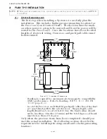
4-3.5 Tach Sensor Harness (required for Active Synchronization)
A) At the Processors, remove the watertight seals from the Tach
Sender pigtail plugs.
B) At the Port Processor, insert the grey, four pin plug into the
Tach Sender pigtail plug.
C) Run the cable to the source of the Tach signal.
D) Connect the conductors to the Tach source in the appropriate
manner, keeping in mind that some sources are polarity sensi-
tive. (black- negative, red- positive)
E) Repeat steps A) thru C) on the Starboard side.
4-3.6 Additional 9000 Series Harnesses
4-3.6.1 Throttle Harness
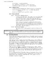
The appropriate Throttle Harness should have been
selected in Section 3-1.4.1, page 3-6. The Processors Throt-
tle pigtail connects directly to the engine interface using
this Throttle Wire Harness.
A) Connect the plug end of the Harness into the Throttle
pigtail connector at the Processor.
B) Run the cable to the engine interface.
C) Refer to the engine documentation for termination
points at the engine interface.
D) If Twin Screw, repeat steps A) thru C) on the opposite
side.
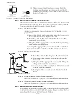
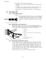
4-3.6.2 Clutch Harness
A) Plug the grey, 12 pin plug into the Clutch pigtail connec-
tor at the Processor.
B) Run the cables to the Ahead and Astern solenoids at the
transmission.
C) Plug the DIN connector into the Ahead and Astern Sole-
noids.
D) If Twin Screw, repeat steps A) thru C) on the opposite
side.
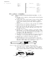
4-3.6.3 Clutch/Troll Harness
A) Plug the grey, 12 pin plug into the Clutch pigtail connec-
tor at the Processor.
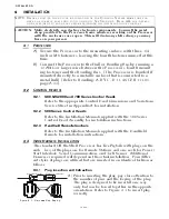
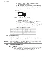
CAUTION: Electro-static discharge can damage this equipment. Whenever the Cover is
removed, you must be grounded to the chassis with the Anti-static Wrist
Strap provided. Failure to do so may cause permanent damage to the elec-
tronic circuits.
NOTE: E
NSURE
P
ORT
P
ROCESSOR
CONNECTS
TO
THE
P
ORT
S
OLENOID
AND
THE
S
TARBOARD
P
ROCES
-
SOR
CONNECTS
TO
THE
S
TARBOARD
P
ROCESSOR
.
NOTE: E
NSURE
P
ORT
P
ROCESSOR
CONNECTS
TO
THE
P
ORT
S
OLENOID
AND
THE
S
TARBOARD
P
ROCES
-
SOR
CONNECTS
TO
THE
S
TARBOARD
P
ROCESSOR
.
Summary of Contents for ClearCommand 9000 Series
Page 132: ......
Page 133: ...APPENDIX A...
Page 134: ......
Page 139: ......
Page 140: ...Page A 4...
Page 143: ......
Page 144: ...10...
Page 148: ...Page A 18...
Page 149: ...Page A 19 TEMPLATE...
Page 150: ...Page A 20...
Page 152: ...Page A 22...
Page 154: ...Page A 24...
Page 156: ...Page A 26...
Page 157: ...Page A 27 Drawing 11488D 1 Twin Screw Single APS Connection Alternate Remote Switch...
Page 158: ...Page A 28...
Page 159: ...Page A 29 Drawing 11488D 2 Twin Screw Dual APS Connections...
Page 160: ...Page A 30...
Page 161: ...Page A 31 Drawing 11488D 3 APS Notes Page...
Page 162: ...Page A 32...
Page 164: ...Page A 34...
Page 166: ...Page A 36...
Page 170: ...Page A 40...
Page 172: ...Page A 42...
Page 176: ...Page A 46...
Page 178: ...Page C 48 ZF Mathers LLC 12125 Harbour Reach Drive Suite B Mukilteo WA 98275...
Page 179: ...APPENDIX B...
Page 180: ......
Page 234: ...Appendix B 6...
Page 238: ...Appendix B 10...
Page 242: ...Appendix B 14...
Page 247: ...Service Field Test Unit Reference Manual MM13927 Rev E 4 07...
Page 248: ......
Page 250: ...Page ii Table of Contents...
Page 264: ...SERVICE FIELD TEST UNIT MM13927 RvD 10 03 Page 3 2...
Page 265: ...APPENDIX C...
Page 266: ......
Page 267: ...Appendix C 1 Drawing 12284A 1 ClearCommand Diagram all options...
Page 268: ...Appendix C 2...
Page 269: ...Appendix C 3 Drawing 12284A 2 ClearCommand Circuit Board Connections...
Page 270: ...Appendix C 4...
Page 271: ...Appendix C 5 Drawing 12284A 3 ClearCommand Drawing Notes Page...
Page 272: ...Appendix C 6...


