INSTALLATION
Page4-20
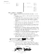
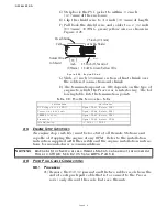
B) If the throttle lever is at the opposite side from the push-pull
cable, change the Throttle Servo Direction E0 as described in
Section 5-5.2.7.6, page 5-10.
C) Adjust the ball joint on the Throttle cable to match the throttle
lever at the Idle stop position.
D) Ensure that adequate cable threads are showing.
E) Tighten the jam nut.
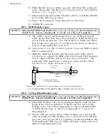
4-6.3 Shift Selector Lever
A) Check the engine and transmission to see if the push-pull
cable anchor brackets have been installed. If the brackets are
not on the transmission, select from Morse Clutch and Throt-
tle Kit Selection, page A-39, or fabricate brackets as shown in
Universal Mounting Kit, page A-41.
B) Turn power ON to the Control System, to ensure that Neutral/
Idle is commanded.
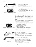
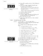
C) With the Shift Push-Pull cable disconnected at the clutch
selector lever, adjust the Shift cable’s ball joint at the transmis-
sion to align with the clutch selector lever at Neutral. The
push-pull cable must form a 90 degree angle to the clutch
selector lever. (Refer to Figure 4-30:)
D) Connect the ball joint to the clutch selector lever.
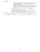
4-6.4 Trolling Valve Selector Lever
A) Check the trolling valve to see if the push-pull cable anchor
brackets have been installed. If the bracket are not on the
trolling valve, select from Appendix A - Morse Standard Kits
or fabricate brackets as shown in Appendix A - Universal
Mounting Kit.
B) Observe the present position of the trolling valve push-pull
cable in relation to the trolling valve selector lever in the full
pressure (lock-up) position. Depending on the installation, the
Troll push-pull cable may be fully extended or fully retracted
when at maximum pressure.
CAUTION: Misadjusted Shift Push-Pull Cables can cause damage to the Transmission’s
Clutch Pack. Ensure adjustments are made correctly and completely.
Figure 4-30: Shift Push-Pull Cable Neutral Connection at Transmission
CAUTION: Misadjusted Troll Push-Pull Cables can cause damage to the Transmission’s
Clutch Pack. Ensure adjustments are made correctly and completely.
90
7 3/8 inches
(187mm)
12267
Anchor
Bracket
Transmission Selector
Lever in Neutral Position
Summary of Contents for ClearCommand 9000 Series
Page 132: ......
Page 133: ...APPENDIX A...
Page 134: ......
Page 139: ......
Page 140: ...Page A 4...
Page 143: ......
Page 144: ...10...
Page 148: ...Page A 18...
Page 149: ...Page A 19 TEMPLATE...
Page 150: ...Page A 20...
Page 152: ...Page A 22...
Page 154: ...Page A 24...
Page 156: ...Page A 26...
Page 157: ...Page A 27 Drawing 11488D 1 Twin Screw Single APS Connection Alternate Remote Switch...
Page 158: ...Page A 28...
Page 159: ...Page A 29 Drawing 11488D 2 Twin Screw Dual APS Connections...
Page 160: ...Page A 30...
Page 161: ...Page A 31 Drawing 11488D 3 APS Notes Page...
Page 162: ...Page A 32...
Page 164: ...Page A 34...
Page 166: ...Page A 36...
Page 170: ...Page A 40...
Page 172: ...Page A 42...
Page 176: ...Page A 46...
Page 178: ...Page C 48 ZF Mathers LLC 12125 Harbour Reach Drive Suite B Mukilteo WA 98275...
Page 179: ...APPENDIX B...
Page 180: ......
Page 234: ...Appendix B 6...
Page 238: ...Appendix B 10...
Page 242: ...Appendix B 14...
Page 247: ...Service Field Test Unit Reference Manual MM13927 Rev E 4 07...
Page 248: ......
Page 250: ...Page ii Table of Contents...
Page 264: ...SERVICE FIELD TEST UNIT MM13927 RvD 10 03 Page 3 2...
Page 265: ...APPENDIX C...
Page 266: ......
Page 267: ...Appendix C 1 Drawing 12284A 1 ClearCommand Diagram all options...
Page 268: ...Appendix C 2...
Page 269: ...Appendix C 3 Drawing 12284A 2 ClearCommand Circuit Board Connections...
Page 270: ...Appendix C 4...
Page 271: ...Appendix C 5 Drawing 12284A 3 ClearCommand Drawing Notes Page...
Page 272: ...Appendix C 6...


