SET UP
Page5-2
5-1.1 Processor Display LED
5-1.2 Push Buttons
5-1.2.1 Up and Down Push Buttons
Pressing the Up or Down Push Buttons once has the follow-
ing functions:
•
Stops Normal Operation Display (running Processor Part
Number) and activates the Function Menu.
• While in the Function Menu, scrolls through the Function
Codes one at a time.
• When an Error Code (Refer to Section B-1.9, page B-21) is
displayed, scrolls through the error messages one at a
time.
• When in Set Up Mode, increases (Up) or decreases (Down)
the Value one digit at a time.
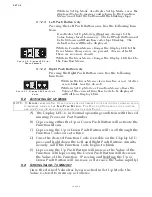
5-1.2.2 Left and Right Push Buttons
Pressing and holding the Left and Right Push Buttons
simultaneously has the following functions:
• Activates Set Up Mode as indicated by the blinking Dis-
play LED. (must hold the buttons until the blinking begins)
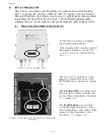
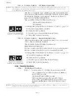
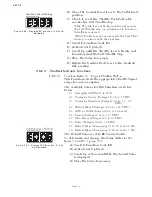
Figure 5-3: Display LED at Normal Operation
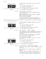
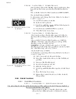
Figure 5-4: Display LED
Designations
• The Processor’s Display LED has four 7-segment LED’s,
which light up to show either letters or numbers.
• The Display LED will have the Processor Part Number
showing in a running pattern during Normal operation
(
Figure 5-3:
)
• The first two digit Display LED’s to the left, indicate the
Function Code, which is alphanumeric.
• The second two digit Display LED’s indicate the numeric
Value that is programmed into the Processor for the
Function Code displayed to the left.
• A decimal point indicator is located on the bottom right
corner of each Display LED.
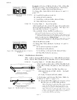
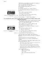
Figure 5-5: Circuit
Board Push Buttons
The Processor has four Push Buttons located on the Circuit
Board. They are identified by the words LEFT, RIGHT, UP
and DOWN silk-screened on the Shield covering the Circuit
Board.
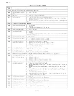
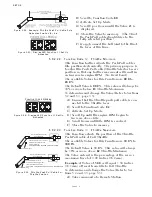
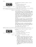
EXAMPLE: Running Processor Part Number during Normal Operation (9210)
Starts the Processor Part Number again, one number at a time.
12309
Summary of Contents for ClearCommand 9000 Series
Page 132: ......
Page 133: ...APPENDIX A...
Page 134: ......
Page 139: ......
Page 140: ...Page A 4...
Page 143: ......
Page 144: ...10...
Page 148: ...Page A 18...
Page 149: ...Page A 19 TEMPLATE...
Page 150: ...Page A 20...
Page 152: ...Page A 22...
Page 154: ...Page A 24...
Page 156: ...Page A 26...
Page 157: ...Page A 27 Drawing 11488D 1 Twin Screw Single APS Connection Alternate Remote Switch...
Page 158: ...Page A 28...
Page 159: ...Page A 29 Drawing 11488D 2 Twin Screw Dual APS Connections...
Page 160: ...Page A 30...
Page 161: ...Page A 31 Drawing 11488D 3 APS Notes Page...
Page 162: ...Page A 32...
Page 164: ...Page A 34...
Page 166: ...Page A 36...
Page 170: ...Page A 40...
Page 172: ...Page A 42...
Page 176: ...Page A 46...
Page 178: ...Page C 48 ZF Mathers LLC 12125 Harbour Reach Drive Suite B Mukilteo WA 98275...
Page 179: ...APPENDIX B...
Page 180: ......
Page 234: ...Appendix B 6...
Page 238: ...Appendix B 10...
Page 242: ...Appendix B 14...
Page 247: ...Service Field Test Unit Reference Manual MM13927 Rev E 4 07...
Page 248: ......
Page 250: ...Page ii Table of Contents...
Page 264: ...SERVICE FIELD TEST UNIT MM13927 RvD 10 03 Page 3 2...
Page 265: ...APPENDIX C...
Page 266: ......
Page 267: ...Appendix C 1 Drawing 12284A 1 ClearCommand Diagram all options...
Page 268: ...Appendix C 2...
Page 269: ...Appendix C 3 Drawing 12284A 2 ClearCommand Circuit Board Connections...
Page 270: ...Appendix C 4...
Page 271: ...Appendix C 5 Drawing 12284A 3 ClearCommand Drawing Notes Page...
Page 272: ...Appendix C 6...

