SET UP
Page5-8
5-6 S
YSTEM
P
ROGRAMMING
A
ND
A
DJUSTMENTS
5-6.1 Processor Functions
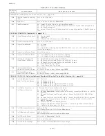
5-6.1.1 Function Code A0 – Processor Identification
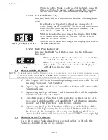
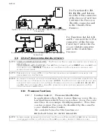
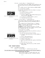
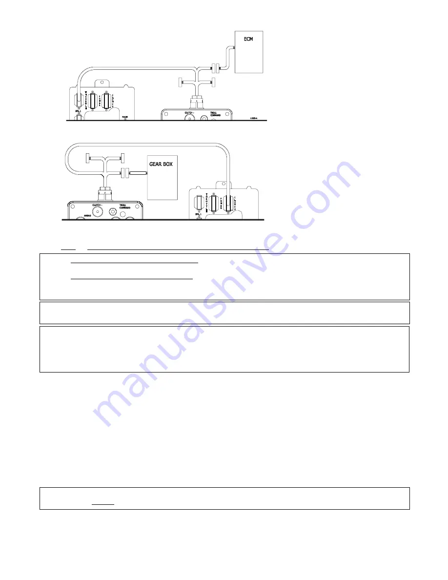
Figure 5-9: E1, E2, E3, E4, E6, L4 Processor, Test Unit, and Multimeter
Connections
For Functions E1, E2,
E3, E4, E6, and L4 con-
nect the 8-Pin connector
of the Service Field Test
Unit into the Processor
Throttle connector and
to the Throttle Wire
Harness.
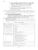
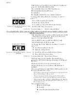
Figure 5-10: L2, L3, C6, and C7 Processor, Test Unit, and Multimeter
Connections
For Functions L2, L3, C6,
and C7 connect the 12-Pin
connector of the Service
Field Test Unit to the Pro-
cessor Clutch connector
and to the Clutch Wire
Harness.
NOTE: SINGLE SCREW APPLICATIONS: T
HE
F
UNCTION
V
ALUES
MAY
BE
ENTERED
AND
STORED
IN
ANY
ORDER
.
TWIN SCREW APPLICATIONS: T
HE
A1 F
UNCTION
MUST
BE
SET
FIRST,
AND
THE
A0 F
UNC
-
TION
MUST
BE
SET
SECOND. T
HE
REST
OF
THE
F
UNCTION
V
ALUES
MAY
BE
ENTERED
AND
STORED
IN
ANY
ORDER
.
NOTE: P
OWER
MUST
BE
TURNED
ON
TO
THE
P
ROCESSORS
WHEN
PROGRAMMING
OR
MAKING
ANY
ADJUSTMENTS
TO
THE
S
YSTEM
.
NOTE: I
N
ORDER
TO
PREVENT
NUISANCE
ALARMS
WHEN
FIRST
SETTING
UP
A
S
YSTEM
,
SOME
F
UNCTION
C
ODES
TAKE
UP
TO
5
MINUTES
TO
BECOME
ACTIVE. T
HE
F
UNCTIONS
AFFECTED
BY
THIS
ARE
THE
FUNCTIONS
THAT
RELY
ON
THE
S
ERIAL
C
OMMUNICATION
,
SUCH
AS
A0, A1, A2, A3, E7,
AND
L0. C
YCLING
POWER
O
FF
,
THEN
O
N
,
EXPEDITES
THESE
FEATURES
MAKING
THE
F
UNC
-
TIONS
AVAILABLE
IMMEDIATELY
.
In applications where there is more than one screw, the sys-
tem must know which Processor is where. Every Processor
must have its own unique identifying number. At no time
can two or more Processors be identified by the same Pro-
cessor Identification Number.
The available Values for this Function are:
00
(Default Value),
01, 02, 03, 04
and
05.
NOTE: I
N
TWIN
SCREW
OR
MORE
APPLICATIONS
,
THE
V
ALUE
OF
F
UNCTION
C
ODE
A0
CAN
BE
CHANGED
ONLY
AFTER
THE
V
ALUE
IN
F
UNCTION
C
ODE
A1
HAS
BEEN
CHANGED
TO
02
OR
HIGHER
.
Summary of Contents for ClearCommand 9000 Series
Page 132: ......
Page 133: ...APPENDIX A...
Page 134: ......
Page 139: ......
Page 140: ...Page A 4...
Page 143: ......
Page 144: ...10...
Page 148: ...Page A 18...
Page 149: ...Page A 19 TEMPLATE...
Page 150: ...Page A 20...
Page 152: ...Page A 22...
Page 154: ...Page A 24...
Page 156: ...Page A 26...
Page 157: ...Page A 27 Drawing 11488D 1 Twin Screw Single APS Connection Alternate Remote Switch...
Page 158: ...Page A 28...
Page 159: ...Page A 29 Drawing 11488D 2 Twin Screw Dual APS Connections...
Page 160: ...Page A 30...
Page 161: ...Page A 31 Drawing 11488D 3 APS Notes Page...
Page 162: ...Page A 32...
Page 164: ...Page A 34...
Page 166: ...Page A 36...
Page 170: ...Page A 40...
Page 172: ...Page A 42...
Page 176: ...Page A 46...
Page 178: ...Page C 48 ZF Mathers LLC 12125 Harbour Reach Drive Suite B Mukilteo WA 98275...
Page 179: ...APPENDIX B...
Page 180: ......
Page 234: ...Appendix B 6...
Page 238: ...Appendix B 10...
Page 242: ...Appendix B 14...
Page 247: ...Service Field Test Unit Reference Manual MM13927 Rev E 4 07...
Page 248: ......
Page 250: ...Page ii Table of Contents...
Page 264: ...SERVICE FIELD TEST UNIT MM13927 RvD 10 03 Page 3 2...
Page 265: ...APPENDIX C...
Page 266: ......
Page 267: ...Appendix C 1 Drawing 12284A 1 ClearCommand Diagram all options...
Page 268: ...Appendix C 2...
Page 269: ...Appendix C 3 Drawing 12284A 2 ClearCommand Circuit Board Connections...
Page 270: ...Appendix C 4...
Page 271: ...Appendix C 5 Drawing 12284A 3 ClearCommand Drawing Notes Page...
Page 272: ...Appendix C 6...


