SET UP
Page5-22
5-6.5 Troll Functions
5-6.5.1 Basic Troll Command Functions
5-6.5.1.4 Function Code L0 – Troll Enable and Control Head Lever
Troll Range
This Function Code tells the Processor whether or
not:
• A 9001 T
ROLLING
A
CTUATOR
OR
INTEGRATED
T
ROLL
C
ONTROL
EXISTS
.
• H
OW
THE
TROLLING
VALVE
IS
TO
BE
CONTROLLED
.
There are four types which can be used to control
any trolling valve. How these different Types func-
tion and when and where they may be applied is
described in the Trolling Actuator’s Installation Man-
ual for the 9001 Trolling Actuator and in Section 2-4,
page 2-2, for Integrated Troll Control.
The available Values are:
00
No Troll (Default Value)
01
20 Degrees – Type 1
02
35 Degrees – Type 2
03
45 Degrees – Type 3 (Throttle limited to 75%).
04
55 Degrees - Type 4 (Throttle limited to 10%).
NOTE: I
F
THE
C
ONTROL
S
YSTEM
DOES
NOT
OFFER
INTEGRATED
T
ROLL
CONTROL
,
A
9001 T
ROLL
A
CTU
-
ATOR
IS
REQUIRED
TO
OFFER
T
ROLLING
V
ALVE
C
ONTROL
.
I
NTEGRATED
T
ROLL
C
ONTROL
A
LL
T
ROLL
F
UNCTIONS
OTHER
THAN
L0
WILL
NOT
BE
DISPLAYED
ON
THE
P
ROCESSOR
D
ISPLAY
LED
IF
F
UNCTION
L0
IS
SET
TO
00. T
O
UTILIZE
T
ROLL
AND
DISPLAY
THE
REST
OF
THE
T
ROLL
F
UNCTIONS
,
A
VALUE
OTHER
THAN
00
NEEDS
TO
BE
ENTERED
FOR
F
UNCTION
L0.
9001 T
ROLL
A
CTUATOR
A
LL
THE
F
UNCTION
C
ODES
RELATING
TO
T
ROLL
WILL
NOT
BE
DISPLAYED
,
UNLESS
AN
EXTERNAL
T
ROLL
A
CTUATOR
(
P
/
N
9001)
IS
CONNECTED
TO
THE
P
ROCESSOR
. I
NSTALLATION
AND
ADJUST
-
MENT
DETAILS
ARE
INCLUDED
WITH
THE
T
ROLL
A
CTUATOR
.
T
HE
FOLLOWING
IS
A
BRIEF
OUTLINE
OF
THE
B
ASIC
T
ROLL
F
UNCTION
ADJUSTMENTS
.
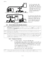
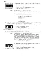
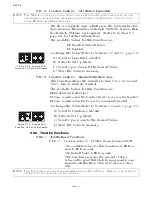
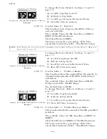
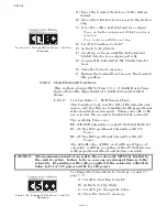
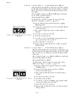
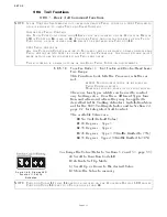
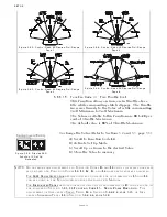
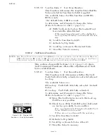
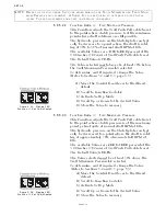
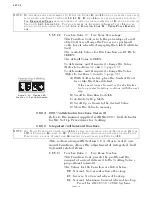
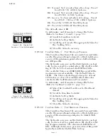
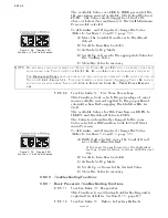
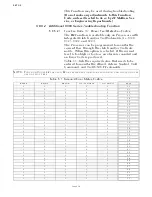
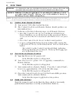
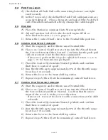
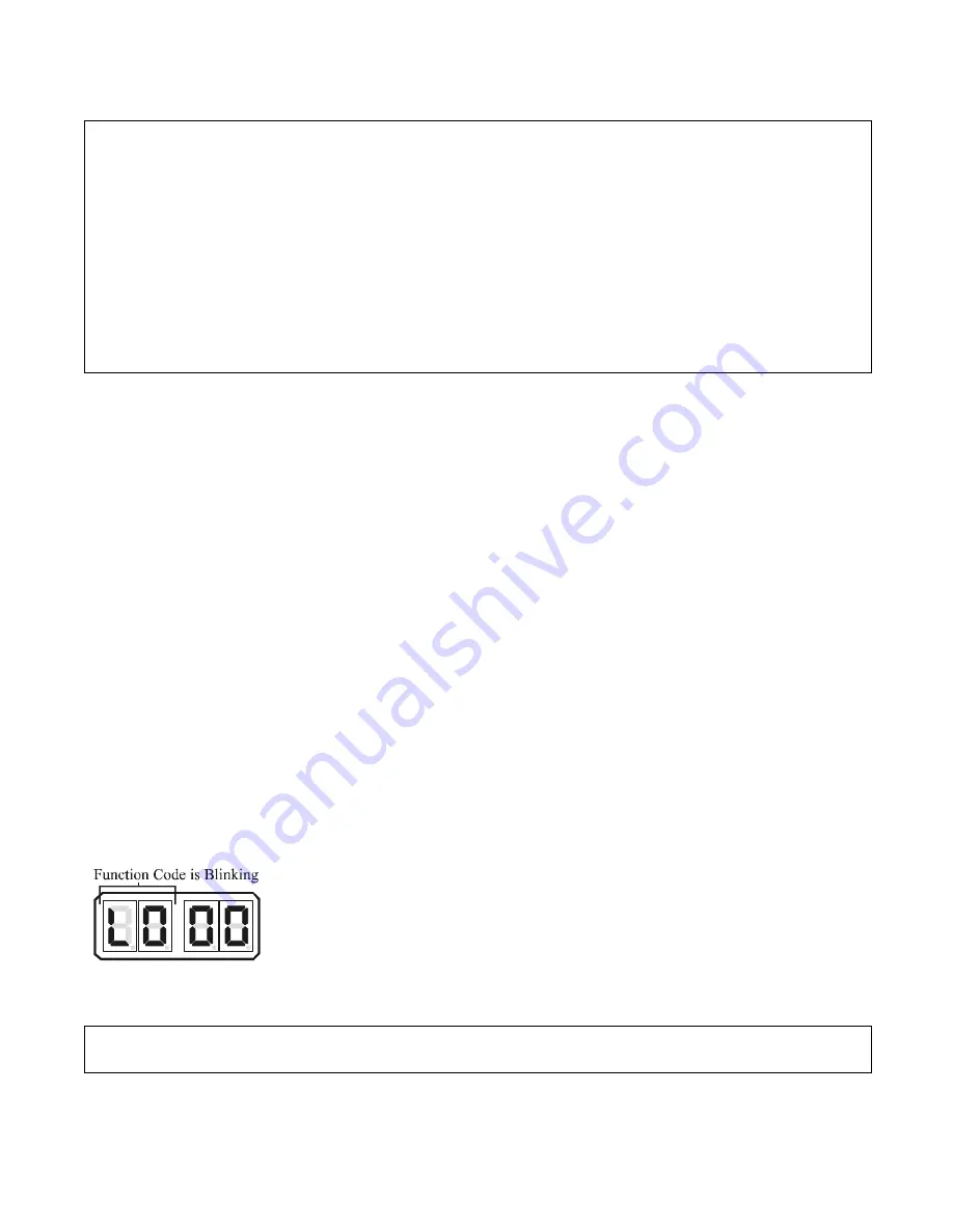
Figure 5-44: Display LED
Function L0 Set Up
Activated
To change the Value (Refer to Sections 5-2 and 5-3, page 5-5):
A) Scroll to Function Code
L0
.
B) Activate Set Up Mode.
C) Scroll Up or Down to the desired Value.
D) Store the Value to memory
NOTE: F
UNCTION
C
ODES
L1
THRU
L6
ARE
NOT
DISPLAYED
ON
THE
P
ROCESSOR
D
ISPLAY
LED
UNLESS
F
UNCTION
C
ODE
L0
IS
SET
TO
A
V
ALUE
OTHER
THAN
00.
Summary of Contents for ClearCommand 9000 Series
Page 132: ......
Page 133: ...APPENDIX A...
Page 134: ......
Page 139: ......
Page 140: ...Page A 4...
Page 143: ......
Page 144: ...10...
Page 148: ...Page A 18...
Page 149: ...Page A 19 TEMPLATE...
Page 150: ...Page A 20...
Page 152: ...Page A 22...
Page 154: ...Page A 24...
Page 156: ...Page A 26...
Page 157: ...Page A 27 Drawing 11488D 1 Twin Screw Single APS Connection Alternate Remote Switch...
Page 158: ...Page A 28...
Page 159: ...Page A 29 Drawing 11488D 2 Twin Screw Dual APS Connections...
Page 160: ...Page A 30...
Page 161: ...Page A 31 Drawing 11488D 3 APS Notes Page...
Page 162: ...Page A 32...
Page 164: ...Page A 34...
Page 166: ...Page A 36...
Page 170: ...Page A 40...
Page 172: ...Page A 42...
Page 176: ...Page A 46...
Page 178: ...Page C 48 ZF Mathers LLC 12125 Harbour Reach Drive Suite B Mukilteo WA 98275...
Page 179: ...APPENDIX B...
Page 180: ......
Page 234: ...Appendix B 6...
Page 238: ...Appendix B 10...
Page 242: ...Appendix B 14...
Page 247: ...Service Field Test Unit Reference Manual MM13927 Rev E 4 07...
Page 248: ......
Page 250: ...Page ii Table of Contents...
Page 264: ...SERVICE FIELD TEST UNIT MM13927 RvD 10 03 Page 3 2...
Page 265: ...APPENDIX C...
Page 266: ......
Page 267: ...Appendix C 1 Drawing 12284A 1 ClearCommand Diagram all options...
Page 268: ...Appendix C 2...
Page 269: ...Appendix C 3 Drawing 12284A 2 ClearCommand Circuit Board Connections...
Page 270: ...Appendix C 4...
Page 271: ...Appendix C 5 Drawing 12284A 3 ClearCommand Drawing Notes Page...
Page 272: ...Appendix C 6...

