CONTROL OPTIONS
Page8-2
8-1.1 Installation
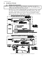
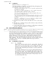
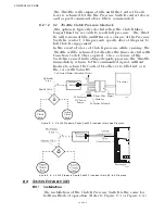
(Refer to Figure 8-1: or Figure 8-2:)
The following items should be considered when designing and
installing the Status Indication Panel:
•
The Power Wire Harness (p/n 13631-#) must be used if an Exter-
nal Alarm is required.
• The Processor’s Alarm Circuit uses a “dry” contact. Therefore,
the polarity of the conductors is not a concern.
• The External Status Indication Circuit must not use the same
power source as the Processor.
• Since the External Status Indication Circuit is activated on a loss
of power to the Processor, an On/Off Switch is strongly recom-
mended.
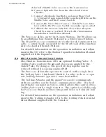
• Figure 8-1: and Figure 8-2: are an example of a suitable circuit,
but not necessarily the only circuit acceptable
.
A) Plug the Power Wire Harness into the Processor’s Power pig-
tail.
B) Run the two-conductor Alarm cable to the location of the Sta-
tus Indication Circuit.
C) Connect the black and red conductors to the Status Indication
Circuit as shown in Figure 8-1: or Figure 8-2:.
8-2 C
LUTCH
P
RESSURE
I
NTERLOCK
The Clutch Pressure Interlock uses a Pressure Switch which moni-
tors the Ahead and Astern Clutch pressures. The Pressure Switch
must have a Normally Open (N.O.) contact that closes when ade-
quate Clutch pressure is reached. The primary function of the
Interlock is to prevent high engine RPM when the Clutch is not
fully engaged. The Interlock option must be selected with Function
Code
C0
. There are two selectable methods of operation as
described below:
8-2.1 C0 Methods of Operation
8-2.1.1 01 - Installed
When selected, the Interlock will command the Throttle to
Idle, if low or a loss of pressure occurs while cruising. The
Interlock is activated when the Pressure Switch’s contact
opens for the minimum period of time selected with Func-
tion Code
C1
.
If adequate Clutch pressure is not reached in the time pro-
grammed in Function Code
E5
, throttle will be allowed to
increase above Idle. The Throttle will remain at this com-
manded speed for the time programmed in Function Code
C1
and then returned to Idle, unless adequate pressure is
reached during this time.
NOTE:
T
HE
C
LUTCH
P
RESSURE
I
NTERLOCK
C0
MUST
BE
SET
TO
BE
USED
. R
EFER
TO
THE
S
ECTION
5-
5.3.8.9,
PAGE
5-12,
FOR
F
UNCTION
C
ODE
C0 – C
LUTCH
P
RESSURE
I
NTERLOCK
Summary of Contents for ClearCommand 9000 Series
Page 132: ......
Page 133: ...APPENDIX A...
Page 134: ......
Page 139: ......
Page 140: ...Page A 4...
Page 143: ......
Page 144: ...10...
Page 148: ...Page A 18...
Page 149: ...Page A 19 TEMPLATE...
Page 150: ...Page A 20...
Page 152: ...Page A 22...
Page 154: ...Page A 24...
Page 156: ...Page A 26...
Page 157: ...Page A 27 Drawing 11488D 1 Twin Screw Single APS Connection Alternate Remote Switch...
Page 158: ...Page A 28...
Page 159: ...Page A 29 Drawing 11488D 2 Twin Screw Dual APS Connections...
Page 160: ...Page A 30...
Page 161: ...Page A 31 Drawing 11488D 3 APS Notes Page...
Page 162: ...Page A 32...
Page 164: ...Page A 34...
Page 166: ...Page A 36...
Page 170: ...Page A 40...
Page 172: ...Page A 42...
Page 176: ...Page A 46...
Page 178: ...Page C 48 ZF Mathers LLC 12125 Harbour Reach Drive Suite B Mukilteo WA 98275...
Page 179: ...APPENDIX B...
Page 180: ......
Page 234: ...Appendix B 6...
Page 238: ...Appendix B 10...
Page 242: ...Appendix B 14...
Page 247: ...Service Field Test Unit Reference Manual MM13927 Rev E 4 07...
Page 248: ......
Page 250: ...Page ii Table of Contents...
Page 264: ...SERVICE FIELD TEST UNIT MM13927 RvD 10 03 Page 3 2...
Page 265: ...APPENDIX C...
Page 266: ......
Page 267: ...Appendix C 1 Drawing 12284A 1 ClearCommand Diagram all options...
Page 268: ...Appendix C 2...
Page 269: ...Appendix C 3 Drawing 12284A 2 ClearCommand Circuit Board Connections...
Page 270: ...Appendix C 4...
Page 271: ...Appendix C 5 Drawing 12284A 3 ClearCommand Drawing Notes Page...
Page 272: ...Appendix C 6...


