CONTROL OPTIONS
Page8-3
The Throttle will remain at Idle until the Control Head’s
lever is returned to Idle, the Pressure Switch contact closes
and a speed command above Idle is commanded.
8-2.1.2 02 - Throttle Clutch Pressure Interlock
This option is typically selected when the Clutch takes
longer than five seconds to reach full pressure. The Throt-
tle will remain at Idle until there is a closure of the Pressure
Switch’s contact. This prevents speeds above Idle prior to
full Clutch engagement.
In the event of a loss of Clutch pressure while cruising, the
Throttle will be returned to Idle after the time selected with
Function Code
C1
has expired. Once a closure of the
Switch is sensed, indicating adequate pressure, the Throttle
immediately returns to the commanded signal, without
having to return the Control Head lever to Idle first, as is
the case with Value
01
.
8-3 S
TATION
E
XPANDER
(SE)
8-3.1 Installation
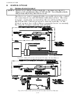
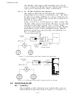
The installation of the Clutch Pressure Switch is the same for
both methods of operation. (Refer to Figure 8-3: or Figure 8-4:)
Figure 8-3: Clutch Pressure Switch with Processor Harness Diagram
Figure 8-4: Clutch Pressure Switch with Processor Hard-Wired Diagram
Processor
Power
Pigtail
Power Wire
Harness
To Starter Solenoid
To External Status Indication Circuit
Pressure
Switch
Hydraulic
Line
Shuttle Valve
Astern
Clutch
Pack
Ahead
Clutch
Pack
To Processor
DC Power
Source
12281
SE
R
IA
L
OP
I
A
LA
R
M
S
T
AT
I
O
N
5
STA RT
INT ERLO CK
EL
EC
-T
H
R
ST
ATI
O
N
3
C
LU
T
C
H
S
TA
TI
O
N
1
JM
P
1
DS 2
DS 1
P1
TB
7
TB
8
TB5
TB 3
TB
6
PB
2
TB
1
23
5
6
8
4
79
1
0
1
1
34
67
25
76
4
3
852
1
76
4
3
85
2
1
76
4
3
1
85
2
12
76
4
3
1
852
J 1
P2
Summary of Contents for ClearCommand 9000 Series
Page 132: ......
Page 133: ...APPENDIX A...
Page 134: ......
Page 139: ......
Page 140: ...Page A 4...
Page 143: ......
Page 144: ...10...
Page 148: ...Page A 18...
Page 149: ...Page A 19 TEMPLATE...
Page 150: ...Page A 20...
Page 152: ...Page A 22...
Page 154: ...Page A 24...
Page 156: ...Page A 26...
Page 157: ...Page A 27 Drawing 11488D 1 Twin Screw Single APS Connection Alternate Remote Switch...
Page 158: ...Page A 28...
Page 159: ...Page A 29 Drawing 11488D 2 Twin Screw Dual APS Connections...
Page 160: ...Page A 30...
Page 161: ...Page A 31 Drawing 11488D 3 APS Notes Page...
Page 162: ...Page A 32...
Page 164: ...Page A 34...
Page 166: ...Page A 36...
Page 170: ...Page A 40...
Page 172: ...Page A 42...
Page 176: ...Page A 46...
Page 178: ...Page C 48 ZF Mathers LLC 12125 Harbour Reach Drive Suite B Mukilteo WA 98275...
Page 179: ...APPENDIX B...
Page 180: ......
Page 234: ...Appendix B 6...
Page 238: ...Appendix B 10...
Page 242: ...Appendix B 14...
Page 247: ...Service Field Test Unit Reference Manual MM13927 Rev E 4 07...
Page 248: ......
Page 250: ...Page ii Table of Contents...
Page 264: ...SERVICE FIELD TEST UNIT MM13927 RvD 10 03 Page 3 2...
Page 265: ...APPENDIX C...
Page 266: ......
Page 267: ...Appendix C 1 Drawing 12284A 1 ClearCommand Diagram all options...
Page 268: ...Appendix C 2...
Page 269: ...Appendix C 3 Drawing 12284A 2 ClearCommand Circuit Board Connections...
Page 270: ...Appendix C 4...
Page 271: ...Appendix C 5 Drawing 12284A 3 ClearCommand Drawing Notes Page...
Page 272: ...Appendix C 6...


