PERIODIC CHECKS AND MAINTENANCE
Page9-1
9
PERIODIC CHECKS AND MAINTENANCE
The items listed below should be checked on an annual basis or
less, when noted:
9-1 C
ONTROL
H
EADS
• Check the terminal strip for signs of corrosion or a loose connec-
tion.
• If used, disconnect the Deutsch connector and check the pins and
sockets for signs of moisture and corrosion.
9-2 P
ROCESSOR
• Check all terminal connections for signs of corrosion or loose con-
nections.
• Un-plug and inspect all Deutsch connectors for signs of moisture
or corrosion.
• While in the vicinity of the Processor, move the Station-in-Com-
mand’s lever. If the Servo’s are excessively noisy, apply a light
coating of silicone grease to the stainless steel lead screws. If
there are no Stations in close proximity to the Processor(s), use a
Field Service Control Head or have someone assist.
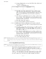
9-2.1 Throttle Servo Processor
•
Check mechanical connections within the Processor and at the
Throttle selector lever.
• Check the mechanical movement of the Throttle lever from Idle to
Full. Ensure that the cable does not bind while positioning the
Throttle at Idle or Full speed.
9-2.2 Clutch Servo Processor
• Check mechanical connections within the Processor and at the
Transmission selector lever.
• Check the mechanical movement of the Clutch selector lever from
Neutral to Ahead, and Neutral to Astern. Ensure that the cable does
not bind while positioning the Control Head lever at Ahead or
Astern. Ensure that the Clutch selector lever and the Push-Pull cable
form a 90 degree angle at Neutral.
9-2.3 Troll Integrated Servo Processor
• Check mechanical connections within the Processor and at the Troll
selector levers.
• Check the mechanical movement of the Troll selector lever from
Lock-up to Minimum pressure and back to Lock-up. Ensure that the
cable moves smoothly and does not bind while positioning the Con-
trol Head lever.
9-3 P
OWER
S
UPPLY
9-3.1 Battery
WARNING: B
ATTERIES
CONTAIN
SULFURIC
ACID
AND
EMIT
HYDROGEN
GAS
WHILE
CHARGING
.
T
HEREFORE
,
SPECIFIC
SAFETY
PRECAUTIONS
MUST
BE
ADHERED
TO
WHILE
HANDLING
AND
SERVICING
. S
PECIFIC
INFORMATION
ON
HANDLING
AND
SERVICING
BATTERIES
CAN
BE
OBTAINED
FROM
THE
B
ATTERY
C
OUNCIL
I
NTERNATIONAL
, B
ATTERY
S
ERVICE
M
ANUAL
.
Summary of Contents for ClearCommand 9000 Series
Page 132: ......
Page 133: ...APPENDIX A...
Page 134: ......
Page 139: ......
Page 140: ...Page A 4...
Page 143: ......
Page 144: ...10...
Page 148: ...Page A 18...
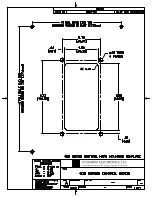
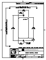
Page 149: ...Page A 19 TEMPLATE...
Page 150: ...Page A 20...
Page 152: ...Page A 22...
Page 154: ...Page A 24...
Page 156: ...Page A 26...
Page 157: ...Page A 27 Drawing 11488D 1 Twin Screw Single APS Connection Alternate Remote Switch...
Page 158: ...Page A 28...
Page 159: ...Page A 29 Drawing 11488D 2 Twin Screw Dual APS Connections...
Page 160: ...Page A 30...
Page 161: ...Page A 31 Drawing 11488D 3 APS Notes Page...
Page 162: ...Page A 32...
Page 164: ...Page A 34...
Page 166: ...Page A 36...
Page 170: ...Page A 40...
Page 172: ...Page A 42...
Page 176: ...Page A 46...
Page 178: ...Page C 48 ZF Mathers LLC 12125 Harbour Reach Drive Suite B Mukilteo WA 98275...
Page 179: ...APPENDIX B...
Page 180: ......
Page 234: ...Appendix B 6...
Page 238: ...Appendix B 10...
Page 242: ...Appendix B 14...
Page 247: ...Service Field Test Unit Reference Manual MM13927 Rev E 4 07...
Page 248: ......
Page 250: ...Page ii Table of Contents...
Page 264: ...SERVICE FIELD TEST UNIT MM13927 RvD 10 03 Page 3 2...
Page 265: ...APPENDIX C...
Page 266: ......
Page 267: ...Appendix C 1 Drawing 12284A 1 ClearCommand Diagram all options...
Page 268: ...Appendix C 2...
Page 269: ...Appendix C 3 Drawing 12284A 2 ClearCommand Circuit Board Connections...
Page 270: ...Appendix C 4...
Page 271: ...Appendix C 5 Drawing 12284A 3 ClearCommand Drawing Notes Page...
Page 272: ...Appendix C 6...


