PERIODIC CHECKS AND MAINTENANCE
Page9-2
The following tests should be performed in the intervals
specified:
9-3.1.1 Quarterly (Every 3 Months)
•
Check the level of the water (electrolyte) within the Lead-Acid
batteries. The plates must be covered. If not, add a small
amount of distilled water.
• Check the voltage of the battery. The battery must have a
chance to “rest” (no charging and no load for a couple of
hours) prior to testing. The following table represents a fully
charged battery:
• Check the battery terminals for signs of corrosion, acid build-
up or loose connections.
9-3.1.2 Semi-Annually (Every 6 Months)
• Check the specific gravity of your Lead-Acid battery(s) with a
Hydrometer. The reading for a fully charged lead acid battery
is 1.260 to 1.280.
9-3.1.3 Annually (Every 12 Months)
The tests performed on quarterly and semi-annual basis,
give a relatively good indication of the batteries’ health.
However, the only way to accurately determine the actual
health of your battery is to perform a Battery Load Test.
• There are two types of Battery Load Tests performed in
the field, Performance and Service. In order to determine
the actual health of your battery a Performance Load Test
is recommended. The Service Load Test determines how
well your battery performs in the boat and doesn’t take
into account the battery’s original rating, which could
result in misleading results. The Performance Load Test
places an accurate load on the battery and compares the
results to the battery manufacture’s specification. The bat-
tery should be replaced if the results are 80% or less than
the manufacture specifications.
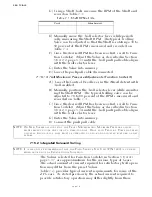
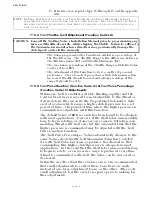
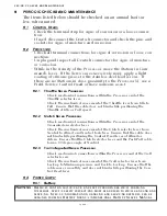
9-3.2 Power Cables, Distribution Panels, etc.
• Check all of the connections from the battery to the DC Distri-
bution Panel to the APS for loose or corroded connections.
• Measure the voltage at the battery and at the Processor while
the Clutch or Throttle Servo is driving. There should be no
CAUTION: In many newer batteries, the vent cap is permanently attached, preventing
access to the electrolyte for water level and specific gravity tests. Attempting to
pry off these caps could result in premature battery failure.
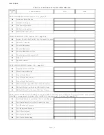
Table 9-1: Fully Charged Battery
Lead Acid Batteries
Gel Cell or AGM Batteries
12V – 12.6
TO
12.8V
12V – 12.4
TO
12.6V
24V – 25.2
TO
25.6V
24V – 25.0
TO
25.4V
WARNING: T
HE
B
ATTERY
L
OAD
T
EST
SHOULD
BE
PERFORMED
BY
A
QUALIFIED
M
ARINE
E
LECTRI
-
CIAN
ONLY
.
Summary of Contents for ClearCommand 9000 Series
Page 132: ......
Page 133: ...APPENDIX A...
Page 134: ......
Page 139: ......
Page 140: ...Page A 4...
Page 143: ......
Page 144: ...10...
Page 148: ...Page A 18...
Page 149: ...Page A 19 TEMPLATE...
Page 150: ...Page A 20...
Page 152: ...Page A 22...
Page 154: ...Page A 24...
Page 156: ...Page A 26...
Page 157: ...Page A 27 Drawing 11488D 1 Twin Screw Single APS Connection Alternate Remote Switch...
Page 158: ...Page A 28...
Page 159: ...Page A 29 Drawing 11488D 2 Twin Screw Dual APS Connections...
Page 160: ...Page A 30...
Page 161: ...Page A 31 Drawing 11488D 3 APS Notes Page...
Page 162: ...Page A 32...
Page 164: ...Page A 34...
Page 166: ...Page A 36...
Page 170: ...Page A 40...
Page 172: ...Page A 42...
Page 176: ...Page A 46...
Page 178: ...Page C 48 ZF Mathers LLC 12125 Harbour Reach Drive Suite B Mukilteo WA 98275...
Page 179: ...APPENDIX B...
Page 180: ......
Page 234: ...Appendix B 6...
Page 238: ...Appendix B 10...
Page 242: ...Appendix B 14...
Page 247: ...Service Field Test Unit Reference Manual MM13927 Rev E 4 07...
Page 248: ......
Page 250: ...Page ii Table of Contents...
Page 264: ...SERVICE FIELD TEST UNIT MM13927 RvD 10 03 Page 3 2...
Page 265: ...APPENDIX C...
Page 266: ......
Page 267: ...Appendix C 1 Drawing 12284A 1 ClearCommand Diagram all options...
Page 268: ...Appendix C 2...
Page 269: ...Appendix C 3 Drawing 12284A 2 ClearCommand Circuit Board Connections...
Page 270: ...Appendix C 4...
Page 271: ...Appendix C 5 Drawing 12284A 3 ClearCommand Drawing Notes Page...
Page 272: ...Appendix C 6...

