SERVICE FIELD TEST UNIT
MM13927 RvD 10/03 Page 2-9
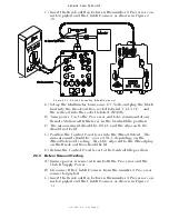
2-3 TROLL TESTING
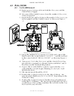
2-3.1 Troll On/Off Solenoid
A) Ensure power is removed from both the Processor and the
Clutch Power Supply.
B) Disconnect the Clutch Harness from the number
3
Processor
connector/pigtail.
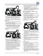
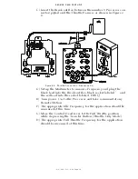
C) Insert the Break-out Box between the number
3
Processor con-
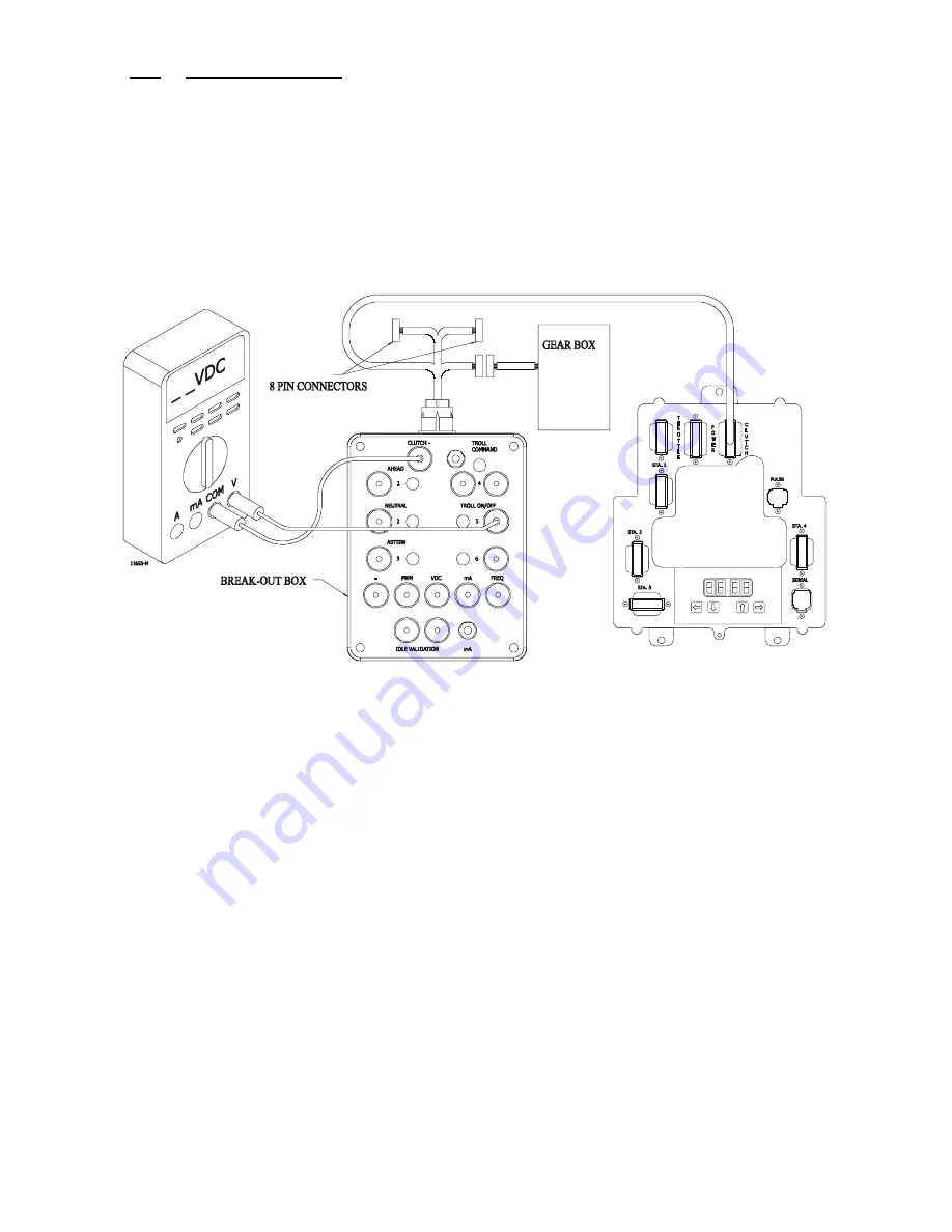
nector/pigtail and the Clutch Harness as shown in Figure 2-
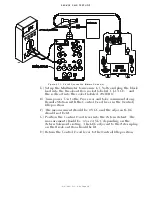
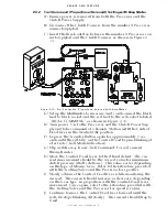
D) Set up the Multimeter to measure DC Volts and connect the
black lead to the socket labeled “CLUTCH –“ and the red lead
to the socket labeled “TROLL ON/OFF” as shown in Figure 2-
E) Turn power ‘On’ to the Processor and the Clutch Power Sup-
ply and take command at a Remote Station with the Control
Head lever in the Neutral/Idle position.
F) Depress the Transfer Button again for approximately 2 sec-
onds until the red LED begins blinking at a fast rate (Troll
Mode Indication).
G) The measurement should be 0 VDC.
H) Position the Control Head lever to the Ahead detent. The
measurement should now be 12 or 24 VDC, depending on the
Solenoid’s rating.
I) Position the Control Head lever further forward while moni-
toring the DC Voltmeter. The measurement should go from 12
or 24 VDC to 0 VDC at the same time the red LED on the Con-
trol Head becomes lit solid.
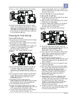
Figure 2-12: Troll Connection (ON/OFF Solenoid)
Summary of Contents for ClearCommand 9000 Series
Page 132: ......
Page 133: ...APPENDIX A...
Page 134: ......
Page 139: ......
Page 140: ...Page A 4...
Page 143: ......
Page 144: ...10...
Page 148: ...Page A 18...
Page 149: ...Page A 19 TEMPLATE...
Page 150: ...Page A 20...
Page 152: ...Page A 22...
Page 154: ...Page A 24...
Page 156: ...Page A 26...
Page 157: ...Page A 27 Drawing 11488D 1 Twin Screw Single APS Connection Alternate Remote Switch...
Page 158: ...Page A 28...
Page 159: ...Page A 29 Drawing 11488D 2 Twin Screw Dual APS Connections...
Page 160: ...Page A 30...
Page 161: ...Page A 31 Drawing 11488D 3 APS Notes Page...
Page 162: ...Page A 32...
Page 164: ...Page A 34...
Page 166: ...Page A 36...
Page 170: ...Page A 40...
Page 172: ...Page A 42...
Page 176: ...Page A 46...
Page 178: ...Page C 48 ZF Mathers LLC 12125 Harbour Reach Drive Suite B Mukilteo WA 98275...
Page 179: ...APPENDIX B...
Page 180: ......
Page 234: ...Appendix B 6...
Page 238: ...Appendix B 10...
Page 242: ...Appendix B 14...
Page 247: ...Service Field Test Unit Reference Manual MM13927 Rev E 4 07...
Page 248: ......
Page 250: ...Page ii Table of Contents...
Page 264: ...SERVICE FIELD TEST UNIT MM13927 RvD 10 03 Page 3 2...
Page 265: ...APPENDIX C...
Page 266: ......
Page 267: ...Appendix C 1 Drawing 12284A 1 ClearCommand Diagram all options...
Page 268: ...Appendix C 2...
Page 269: ...Appendix C 3 Drawing 12284A 2 ClearCommand Circuit Board Connections...
Page 270: ...Appendix C 4...
Page 271: ...Appendix C 5 Drawing 12284A 3 ClearCommand Drawing Notes Page...
Page 272: ...Appendix C 6...


