background image

Installation

17

EN_3224.758.102c_2020_02

4   Installation

V-DRIVE gearbox is not flanged directly on to the engine. Make sure that the connecting cardan shaft does not transmit 
vibration which could damage the transmission. V-DRIVE gearbox is installed separately, with a drive shaft and the 
foundation mounting can be either rigid or elastic.
If necessary, in addition to the normal flexible coupling fitted to the engine, fit an extra damper to absorb the vibration 
caused by an imperfect alignment.

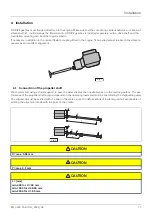
4.1   Connection of the propeller shaft

We recommend using a thrust support to ease the axial stresses that inevitably bear on the marine gearbox. The per-
formance of the propeller shaft support depends on the operating loads and must be specified by the shipbuilding yard.
The alignment must be verified with the boat in the water, since the deformations of a submerged hull are capable of 
altering the alignment made with the boat on the cradle.

X = max. 0.05 mm

Y = max. 0.1 mm

L = [mm]
min. 500 for d < 60 mm
min. 1000 for d 60-90 mm
min. 2000 for d > 90 mm

Fig. 1

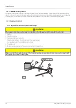
Fig. 2

 CAUTION

 CAUTION

 CAUTION

Summary of Contents for 400 Family

Page 1: ...ZF 400 Family Operating Instructions...

Page 2: ...t is protected by copyright Complete or partial reproduction or dissemination of this document is prohibited without the consent of ZF Friedrichshafen AG Infringements lead to civil and criminal prose...

Page 3: ...g 14 2 Technical data 15 2 1 Types of oil 15 2 1 1 Lubricant class 04A 15 2 1 2 Lubricant class 04B 15 2 1 3 Lubricant class 04C 15 3 Emergency control 16 3 1 Electrical system breakdown 16 4 Installa...

Page 4: ...Index 4 EN_3224 758 102c_2020_02...

Page 5: ...entioned in the offers issued by ZF Sales Dept Notice Read this handbook before proceeding with the installation The following symbols are used to highlight important in formation on technical reliabi...

Page 6: ...can lead to serious injuries or death when not avoided Describes a dangerous situation that can lead to serious injuries or death when not avoided Describes a dangerous situation that can lead to mino...

Page 7: ...the relative operating manual Further copies of this manual or of other technical documentation can be obtained from ZF Padova S r l Via Penghe 48 35010 Caselle di Selvazzano PD Italy Tel 39 049 8299...

Page 8: ...types of operation Neutral The output shaft 2 connected to the propeller shaft does not transmit any rotation The clutches are disengaged Engine rotation The output shaft 2 connected to the propeller...

Page 9: ...n of motion can be reversed with the engine at full speed Repeatedly reversing the drive with the engine running at maximum speed will considerably shorten the life of the clutches Before putting the...

Page 10: ...in plugs 4 Rear half housing 5 Front half housing 6 Oil cooler 7 Lifting eyebolt 8 Oil dipstick 9 Control valve 10 Solenoid valve 11 Oil filter 12 Oil pump 13 Strainer Screen filter 14 Filler plug 15...

Page 11: ...r 5 Drain plugs 6 Rear half housing 7 Front half housing 8 Oil dipstick 9 Breather 10 Oil cooler 11 Filler plug 12 Shift control linkage bracket 13 Control valve 14 Control valve lever 15 1 8 NPTF pre...

Page 12: ...il pump 3 Output shaft 4 Strainer Screen filter 5 Drain plugs 6 Rear half housing 7 Front half housing 8 Oil dipstick 9 Breather 10 Oil cooler 11 Filler plug 12 Control valve 13 1 8 NPTF pressure conn...

Page 13: ...0 rpm Depending on the marine gearbox s reduction ratio the propeller s dimensions and the features of the boat the actual rotation speed of the propeller can be reduced by a percentage varying betwee...

Page 14: ...ly for 8 hours Check that the oil temperature does not exceed 80 C When the engine is off the position of the operating lever is irrelevant When installing the shift control linkage make sure the trav...

Page 15: ...gine oil Viscosity class SAE 30 in warm countries or when the temperature in the oil pan exceeds 80 C SAE 40 is also ac cepted 2 1 3 Lubricant class 04C Multi grade engine oil Viscosity classes SAE 5W...

Page 16: ...otection cap 2 Fig 2 press button 3 Fig 3 and turn it counter clockwise a valve closed normal position b valve open emergency position To reset the electrical control valve tighten the protection cap...

Page 17: ...r to absorb the vibration caused by an imperfect alignment 4 1 Connection of the propeller shaft We recommend using a thrust support to ease the axial stresses that inevitably bear on the marine gearb...

Page 18: ...agrams 4 3 Alignment method 4 3 1 Alignment method with parallel face flanges 1 Engine 2 Flexible coupling 3 Variable length universal joint Selected according to the instructions of the manufacturer...

Page 19: ...nd install the universal joint make sure that the longitudinal axes of the flexible coupling alignment shafts and marine gearbox input shaft are aligned on the same vertical plane Make sure that the t...

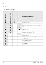
Page 20: ...inspection Oil level inspection Tighten all the screw connections accessible from the out side Remote control adjustment Intake filter check Transmission external cleaning Lubrication of external mov...

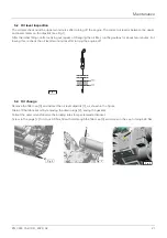
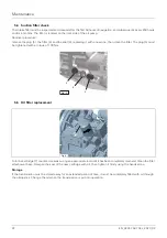
Page 21: ...the gearbox for about two minutes Fol lowing this recheck the oil level two minutes after turning the engine off 5 3 Oil change Remove the filler cap 3 and extract the oil level dipstick 1 as shown i...

Page 22: ...then clean the filter The plug 5 must be tightened with a torque of 100 Nm 5 5 Oil filter replacement Turn the cartridge 7 counter clockwise using an appropriate tool until it has been completely remo...

Page 23: ...ral position of the control valve lever Perform the same check on the Flying Bridge if present This operation must be verified also after the first few hours of operation INSPECTION OF THE FLEXIBLE CO...

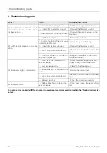
Page 24: ...osition of the gear enga gement selection lever Adjust the gear shift linkage 3 Intake filter partially clogged Remove the filter and clean it 4 Use of a non recommended oil Replace the oil with a rec...

Page 25: ...o support its customers Roughly 400 partners worldwide are dedicated to sales after sales services and assistance for ZF marine products To find the nearest ZF support center contact the regional cent...

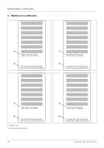
Page 26: ...rift A B Ore lavoro Heures de marche Horas de trabajo Arbeitsstunden Data timbro firma Date timbre signature Fecha sello firma Datum Stempel Unterschrift A B Ore lavoro Heures de marche Horas de traba...

Page 27: ......
Page 28: ...ZF Padova S r l 35010 Caselle di Selvazzano PD Via Penghe 48 Telefono Phone 39 049 8299485 Telefax Fax 39 049 8299560 www zf com...

Reviews: