Operating Instructions
2K800/2K801/2K802
Initial
Installation
EN 4161.758.103m – 2015-10
17
Fill the gearbox with oil and connect up the
recirculating lubrication system and the power
supply. The breather outlet must always be at the
top, regardless of the installation position. Tighten
by max. 1 turn if necessary.
The gearbox is now ready for use.
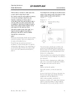
1
st
gear position
A
Brake
disc
B
Sliding
sleeve
CAUTION
The gearboxes can be operated under the same
degrees of protection as those defined for AC
and DC motors.
When setting up, make sure that the motor
cooling air can flow in and out unhindered.
NOTE
Before taking the electric motor/gearbox assembly
into operation, check that the gearbox output can
be turned by hand.
In the case of drive units that are fixed on the
gearbox flange, support the motor on the B-side
so that it does not vibrate.
3.5
Output
3.5.1
Version with belt output
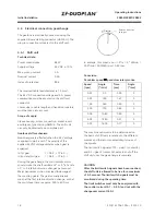
The belt pulley must be centered on the outer
diameter of the output flange (tolerance K6),
fastened with the bolts so that it is frictionally
engaged and secured. Comply with the specified
tightening torques.
The belt pulley should be balanced to quality 6.3
as per VDI Directive 2060 in order to ensure low-
vibration operation.
CAUTION
Note the maximum specified tensioning force
when tightening the belts in order to prevent
bearing overload.
The average belt force must be between the
bearings. When assembling, it must be possible
to easily slide the belt pulley onto the output
shaft. Heat the belt pulley if necessary.
3.5.2
Version with coaxial output
In the case of the version with coaxial output
(shaft stub), also note the balancing type for the
output (see chap. 3.2). The gearbox is delivered
with full-key balancing.
Refer to the installation drawing for the fitted
key dimensions. Always fix the fitted keys using
threaded pins.
3.5.3
Version without output
The output shaft is not supplied by ZF. It is
manufactured by the customer. Refer to the
installation drawing for a proposal of how the
connection point for the output shaft should be
configured with the DIN 5480 profile. Apply a
suitable bolt locking compound (e. g. Loctite no.
275 or no. 243) to the M12 cap screw and tighten
to 115 Nm.


