background image


Maintenance and Installation Instructions


Edition 11.07.2006 

8 of 30 

Installation 

General Instructions 

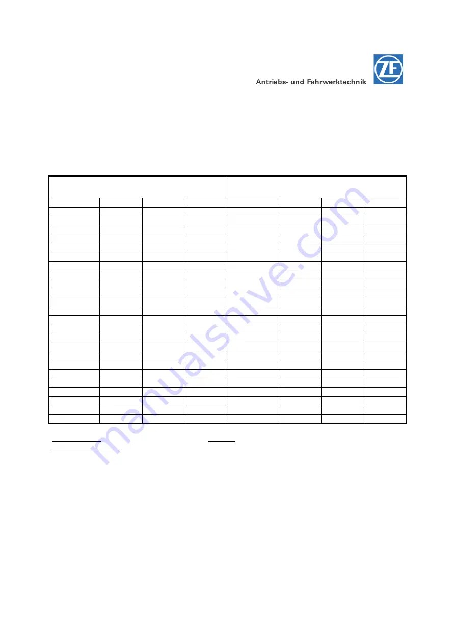
Torque limits in Nm for screws to ZF Standard 148 

Torque limits, if not especially indicated, can be taken from the following list: 
 

Metric ISO-Standard thread DIN 13, 
Sheet 13 

Metric ISO-Fine thread DIN 13, 
Sheet 13 

Size 

8.8 

10.9 

12.9 

Size 

8.8 

10.9 

12.9 

M 4 

2.8 

4.1 

4.8 

M 8x1 

24 

36 

43 

M 5 

5.5 

8.1 

9.5 

M 9x1 

36 

53 

62 

M 6 

9.5 

14 

16.5 

M 10x1 

52 

76 

89 

M 7 

15 

23 

28 

M 10x1.25 

49 

72 

84 

M 8 

23 

34 

40 

M 12x1.25 

87 

125 

150 

M 10 

46 

68 

79 

M 12x1.5 

83 

120 

145 

M 12 

79 

115 

135 

M 14x1.5 

135 

200 

235 

M 14 

125 

185 

215 

M 16x1.5 

205 

300 

360 

M 16 

195 

280 

330 

M 18x1.5 

310 

440 

520 

M 18 

280 

390 

460 

M 18x2 

290 

420 

490 

M 20 

390 

560 

650 

M 20x1.5 

430 

620 

720 

M 22 

530 

750 

880 

M 22x1.5 

580 

820 

960 

M 24 

670 

960 

1100 

M 24x1.5 

760 

1100 

1250 

M 27 

1000 

1400 

1650 

M 24x2 

730 

1050 

1200 

M 30 

1350 

1900 

2250 

M 27x1.5 

1100 

1600 

1850 

M 33 

1850 

2600 

3000 

M 27x2 

1050 

1500 

1800 

M 36 

2350 

3300 

3900 

M 30x1.5 

1550 

2200 

2550 

M 39 

3000 

4300 

5100 

M 30x2 

1500 

2100 

2500 


M 33x1.5 

2050 

2900 

3400 


M 33x2 

2000 

2800 

3300 


M 36x1.5 

2700 

3800 

4450 


M 36x3 

2500 

3500 

4100 


M 39x1.5 

3450 

4900 

5700 


M 39x3 

3200 

4600 

5300 


Friction value

µ

 tot. 0.12

 for screws and nuts 

without

 after-treatment, as well as phosphatized nuts. 

Tightened by hand! 


Summary of Contents for GK20

Page 1: ...1 07 2006 For possible technical modifications of the product described in this manual ZF Gotha GmbH reserve the right to change the product documentations if necessary Technical modifications are to...

Page 2: ...nadequate use of the transmission or the drive unit insufficient maintenance improperly and incompetently performed work and the resulting consequential damages faulty operation ZF Gotha GmbH reserve...

Page 3: ...ge 9 Transport 9 Removal of the corrosion protection 9 Attachment of the Electric Motor 10 Attachment of the electric motor to the transmission 10 Pivoted Connection Steering 12 Mounting of the gear r...

Page 4: ...mission types GK 20 GK 25 GK 30 25 Oil grade for transmission type GK 40 25 Oil capacity 25 Maintenance intervals Transmission 26 Oil Change 26 Drain the transmission oil at GK 20 GK 25 GK 30 26 Drain...

Page 5: ...el foreign to ZF and after expenditures eventually arising from it are excluded from this contractual responsibility This applies also in case of a renouncement of Genuine ZF Spare Parts We did not go...

Page 6: ...ied by ZF are not checked and approved by us either We do not accept any liability or admit any warranty for damages caused by the use of spare parts and accessories which are no original parts from Z...

Page 7: ...g pinion is shown or steering chain as alternative Item 04 Mounting holes optional Item 05 one piece pivoted bogie bearing optional Item 06 Wheel shaft with centering and locating face for drive wheel...

Page 8: ...n housing on the bearing cover side Figure 02 The model identification plate is fixed to the transmission housing side Technical data of the transmission is indicated on the model identification plate...

Page 9: ...20 145 M 12 79 115 135 M 14x1 5 135 200 235 M 14 125 185 215 M 16x1 5 205 300 360 M 16 195 280 330 M 18x1 5 310 440 520 M 18 280 390 460 M 18x2 290 420 490 M 20 390 560 650 M 20x1 5 430 620 720 M 22 5...

Page 10: ...speed of 1000 to 1500 min the transmission is to be driven for approx 2 minutes so that all transmission internal parts are wetted with oil If this is ensured the oil can be drained off again We recom...

Page 11: ...pecial lubrication grease BEM 34 132 onto the splined shaft hub connection Assemble the electric motor Item 1 into the centering seat of the pivot bogie bearing Item 2 and join it cautiously with the...

Page 12: ...tenance and Installation Instructions Edition 11 07 2006 11 of 30 Example for the electric motor attachment without centering ring connection directly to the pivoted bogie bearing Figure 04 05 03 01 0...

Page 13: ...that the boltholes in the pivoted bogie bearing are aligned with the hole pattern of the gear ring and the housing 6 Fasten the pivoted bogie bearing and the gear ring on the mounting construction by...

Page 14: ...A Dim B 0 05 to 0 25 mm bearing preload e Prepare the required shim ring thickness and insert it Figure 07 In order to obtain the bearing preload a gap of 0 05 0 25 mm must exist before between the ho...

Page 15: ...mission housing is positioned into the fitting bore in the transmission top section k Bolt together the transmission top section and the transmission by means of Allen screws Item 02 l The transmissio...

Page 16: ...ion Demounting of the pivoted connection is basically made in reverse order of the mounting Checking of fixing bolts of the pivoted connection The fixing bolts of the pivoted connection see Fig 05 Ite...

Page 17: ...rt water etc the mounting type of the pivoted connection Prior to every relubrication procedure it is necessary to clean the teeth in particular the tooth root Exact relubrication intervals can only b...

Page 18: ...Item 01 on the chain flange Item 02 is made by a chain tensioner Item 03 with an adjustable element Item 04 Sixteen 16 holes Item 05 on the plane face of the chain guideway allow fixing of the chain t...

Page 19: ...ion that no foreign substances or cleaning agents get through the threaded holes Item 01 of the mounting construction hole pattern of the housing inside the transmission 3 Place the chain flange Item...

Page 20: ...ry to use new screws Mounting of the chain tensioner 1 Hang the chain tensioner Item 03 into the requested position on the chain guideway and swivel it so that the tensional pin Item 09 can be hit in...

Page 21: ...ping at the steering stop it is required to consider thrust factors up to 2 5 Pay attention to dampened final stops enabling to obtain as low as possible tractive forces of the chain so that small cha...

Page 22: ...ing chains are currently approved by ZF for GK40 etc see Fig 16 Page 21 Mounting dimensions in mm Single roller chain D E F 10B 1 5 8 x 3 8 335 16 DIN 8187 E 10B 1 DIN 8181 E 210B 12B 1 x 7 16 337 07...

Page 23: ...machining Inadmissible distortions or deformations during fastening of the screws occur due to uneven locating on the frame plate or unevenness in the locating area of the pivoted bogie bearing The pi...

Page 24: ...limited carrying capacities and maximum speeds Damaged worn or deformed drive wheels are not allowed to be repaired or mounted Pay attention that mounting of the drive wheel and the appropriate wheel...

Page 25: ...tructions Edition 11 07 2006 24 of 30 Figure 18 After mounting of a wheel it is mandatory to retighten the wheel nuts and wheel bolts respectively with the specified torque after a mileage of approx 5...

Page 26: ...cants TE ML 17 Lubricant class 17A and 17B Detailed data to the oils grades is found in the Internet under the below mentioned address www zf com Products for Techn Information List of Lubricants The...

Page 27: ...quire the written approval by ZF Oil Change Drain the transmission oil at GK 20 GK 25 GK 30 Do not drain transmission oil into the soil or the sewerage system Pay attention to the type and quantity of...

Page 28: ...n ground and lock the wheels for safety purposes Carefully clean the area around the oil filler and oil drain plug Place a suitable big oil collecting vessel under the oil drain plug Loosen the oil fi...

Page 29: ...t least when oil penetrates at the oil filler plug Attach the oil filler plug Item 01 with a new sealing ring Item 02 Tightening torque 22 Nm Figure 21 Fill in the transmission oil at GK 40 Possibilit...

Page 30: ...ved when the oil level is at the lower edge of the oil filler plug at least when oil penetrates at the oil filler plug Attach the oil filler plug Item 01 with a new sealing ring Item 02 Tightening tor...

Page 31: ...ing torque 34 Nm Oilchange Greasing of the teeth on the pivoted connection Visual inspections Visual inspection for oil leakage General condition of the pivoted connection for extreme conditions see C...

Reviews: