Manual de operaciones
www.zigor.com
53
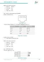
5.6 Battery connection
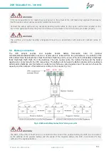
The
UPS
adopts
positive
and
negative
double
battery
framework,
total
30
(optional
32/34/36/38/40/42/44/46/48/50) in series. A neutral cable is retrieved from the joint between the cathode of the
15th (16th/17th/18 th/19th/20 th/21 th/22 th/23 th/24 th/25 th) and the anode of the 16th (17th/18th/19 th/20th/21
th/22 th/23th/24 th/25 th/26 th) of the batteries. Then the neutral cable, the battery Positive and the battery
negative are connected with the UPS respectively. The battery sets between the Battery anode and the neutral are
called positive batteries and that between neutral and cathode are called negative ones. The user can choose the
capacity and the numbers of the batteries according to their desire (Fig. 5-4).
Fig. 5-4 External battery connections for long-run units
WARNING
If the load equipment is not ready to accept power on the arrival of the commissioning engineer then ensure
that the system output cables are safely isolated at their ends
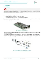
Connect the safety earth and any necessary bonding earth cables to the copper earth screw located on the
floor of the equipment below the power connections. All cabinets in the UPS must be grounded properly.
WARNING
The earthing and neutral bonding arrangement must be in accordance with local and national codes of
practice.
WARNING
The BAT+ of the UPS connect poles is connected to the anode of the positive battery, the BAT-N is connected
to the cathode of the positive battery and the anode of the negative battery, the BAT- is connected to the
cathode of the negative battery.

