background image

ZGR TOWER PRO 1   3 KVA 


Operation manual 

www.zigor.com 

29


Intelligent slot 

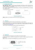
The UPS is equipped with a slot that is designed optionally for either SNMP/Modbus or dry contact cards. 


Fig. 5-4 SNMP/Modbus card 

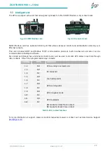
Fig. 5-5 Dry contact card


SNMP/Modbus  card  has  a  standard  RJ45  port  that  allows  advanced  monitor  and  administration  remotely  over 
Ethernet network. 

This  card  includes  SNMP  and  Modbus  TCPIP  communication  protocols,  built-in  webserver  and  also  it  can  be 
communicated via NetAgent software. 

Dry contact card (relays) has a terminal connector and could be used to monitor UPS status in real time through 
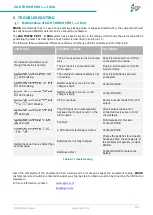
relay contacts.  It has 6 non programmable relay contacts: 

TERMINAL 

TYPE 

FUNCTION 

1-2 

NO 

UPS working in normal mode 

1-3 

NO 

AC mains fail 

1-4 

NC 

1-5 

NO 

Low battery alarm 

1-6 

NC 

1-7 

NO 

UPS warning alarm 

1-8 

NC 

1-9 

NO 

UPS in bypass mode 

1-10 

NC 

1-11 

NO 

UPS fault alarm 

1-12 

NC 


NO means Normally Open contact 
NC means Normally Close contact 

Table 5-1 Dry contact functions 


For more information or support, please consult its respective manual or  contact our Customer Service Support 
((

sac@zigor.com

) . 


Summary of Contents for TOWER PRO 1 kVA

Page 1: ...Operation Manual ZGR TOWER PRO 1 3 KVA Online single phase UPS www zigor com...

Page 2: ......

Page 3: ...formation 17 4 1 3 Alarm list 18 4 1 4 Function of the buttons 20 4 1 5 UPS setting menu 20 Operation modes 22 4 2 1 Normal mode 22 4 2 2 Battery mode 22 4 2 3 Bypass mode 23 4 2 4 Standby mode 23 4 2...

Page 4: ...User Manual or its transmission of any type or by any means be this mechanical or electronic by means of photocopies registration or other information storage or recovery procedure without the permis...

Page 5: ...risk The use for which the unit was designed is defined in the documentation The system shall be exposed only to admissible environmental conditions These are defined in the technical details provided...

Page 6: ...s Do not disconnect the input from the UPS and make sure the UPS is completely off before moving it or reconfiguring the connection otherwise there is a risk of electric shock Only authorized personne...

Page 7: ...ste at the end of its useful life To preserve the environment manage them in accordance with current environmental regulations and requirements in each country or community In case of doubt consult th...

Page 8: ...or corrector which supplies a inverter stage a battery charging circuit and an output filter that provides quality disturbance harmonic free output In case of a mains failure the load supply is guaran...

Page 9: ...s Instantaneous transition from normal to battery mode operation and vice versa as this is a double conversion model there is no failure in the output voltage in transitions between mains and battery...

Page 10: ...rnet SNMP protocol or dry contact cards can be assembled Any of these modules can be used simultaneously with the RS232 and USB ports ECO mode these m providing gr Frequency converter these models can...

Page 11: ...connections Proximity to magnetic fields and high power lamps must be avoided Prevent the UPS being exposed to the sun Do not obstruct the vents as this would prevent the correct dissipation of the he...

Page 12: ...and output must be 3 wire connections phase neutral ground In all cases connections are made by means of IEC type connectors or terminals depending on model Take the following steps into consideration...

Page 13: ...the correct position Fig 3 2 Battery connection with TOWER PRO type cabinets If more autonomy is required than initially acquired additional cabinets of this type can be added In case of internal bat...

Page 14: ...r Install the breaker in accordance with the instructions included with the battery cabinet and check it is open Place and wire the batteries distributed over the cabinet divisions in accordance with...

Page 15: ...hall be restricted to trained personnel A short circuit on the battery terminals or of one of its elements before the breaker or fuse is EXTREMELY DANGEROUS as the current will be limited only by the...

Page 16: ...ad input output alarms or backup times Buttons there are four buttons to control the operation of the UPS Fig 4 1 UPS control panel 4 1 1 LED indicators In the below table is defined the meaning of th...

Page 17: ...when UPS is in battery mode H hours M minutes Indicates warning code warning symbol blinking Indicates fault code error symbol lit Indicates parameter number in setting menu Battery information Indica...

Page 18: ...ns are as below SCREEN DESCRIPTION DISPLAYED CONTENT 01 Input and output voltage 02 Input and output voltage 03 Battery voltage and capacity 04 Internal temperature 05 Power demanded by the load 06 Fi...

Page 19: ...Once per second blinking 27 Mains Input reverse Once per second blinking 28 Bypass Input reverse Once per second blinking 29 Output Short circuit Once per second blinking 30 Input current limit Once...

Page 20: ...seconds to turn off the UPS Factory made it will transfer to bypass mode If transferring to standby mode is desired set parameter 10 in setting menu Setting menu Press this button to exit setting men...

Page 21: ...uts SEGMENT1 Possible values are 1 75 1 84 or 1 92 default 1 75 V Indicates voltage per battery cell 06 End of discharge setting To configure the disconnection of loads connected to priority outputs S...

Page 22: ...s are constantly kept at a Floating or Boost charge voltage In this operation mode control panel shows the current status as below Fig 4 2 Control panel in normal mode 4 2 2 Battery mode If the electr...

Page 23: ...s mode and bypass voltage and or frequency is out of limits Moreover making a configuration in the setting menu the equipment also can be in this operation mode when is powered on or stopped In this o...

Page 24: ...nected to the UPS does not exceed the nominal value It is not recommended to connect high consumption devices or with high start up spikes such as laser printers or motors to the UPS Check the install...

Page 25: ...will start to turn on until transferring to battery mode The display will show the backup time 4 3 4 Regular starts and stops If you plan to start and stop the UPS on a regular basis it is recommendab...

Page 26: ...ly soon Users could switch off some non critical loads to prolong the backup time If there is no more load to be switched off at that time you have to shut down all loads as soon as possible to protec...

Page 27: ...the buzzer sounds it means that there are some problems for UPS operation Users can get the fault code from LCD panel Please check the trouble shooting table in section 6 for details 4 3 10 Operation...

Page 28: ...to UPS USB port and the other side to computer USB port Install UPSilon 2000 software in your computer to monitor UPS status To obtain this software follow steps in the instruction card included with...

Page 29: ...t can be communicated via NetAgent software Dry contact card relays has a terminal connector and could be used to monitor UPS status in real time through relay contacts It has 6 non programmable relay...

Page 30: ...nected Check if all batteries are well connected LED blinking Battery voltage is too high or the charger is fault Contact ZIGOR LED blinking Battery voltage is too low or the charger is fault Contact...

Page 31: ...ith frequency are as follows Monthly o Visual control of correct operation Display and LED indicators indicating correct operation Values within margins No active event o Control of the event history...

Page 32: ...es provide an indication of autonomous operation allow you to detect faulty elements and discover symptoms of premature ageing It is not necessary to discharge the battery completely as this might inv...

Page 33: ...ectricity before handling connections Do not place tools on the batteries Do not place batteries near fire or sources of heat Do not smoke there is a risk of explosion Make sure that the equipment is...

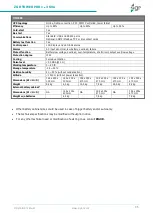
Page 34: ...pport OUTPUT Power 1000 VA 900 W 2000 VA 1800 W 3000 VA 2700 W Power factor 0 9 Phase Phase neutral ground Output voltage 200 208 220 230 240 Vac Voltage regulation 1 Frequency 50 60 3 Hz normal mode...

Page 35: ...ing Forced ventilation Noise level 50 dBA 1 m Working temperature 0 40 C Storage temperature 25 55 C Relative humidity 20 90 without condensation Altitude 1500 m without power reduction Dimensions W H...

Page 36: ...European regulations I LVD Security directive LVD 2014 35 EU about Uninterruptible Power Supply UPS Standard EN 62040 1 2019 II EMC directive 2014 30 EU about electromagnetic compatibility EMC Standar...

Page 37: ...eferring to the Installation Conditions When the customer not clearly proves the systematic realization of regular maintenance operations described in the Operating Manual Equipment deterioration due...

Page 38: ...Portal de Gamarra 28 01013 Vitoria Gasteiz lava Spain 34 945 21 46 00 www zigor com Consulte nuestra web para contactar con la red de delegaciones comerciales Refer to our website in order to contact...

Reviews: