background image

15

16

22

23

24

13

14

1

7

3

2

5

6

6

9

10

6

9

10

20

19

17

18

4

8

12

11

21

6

26

25

27

6

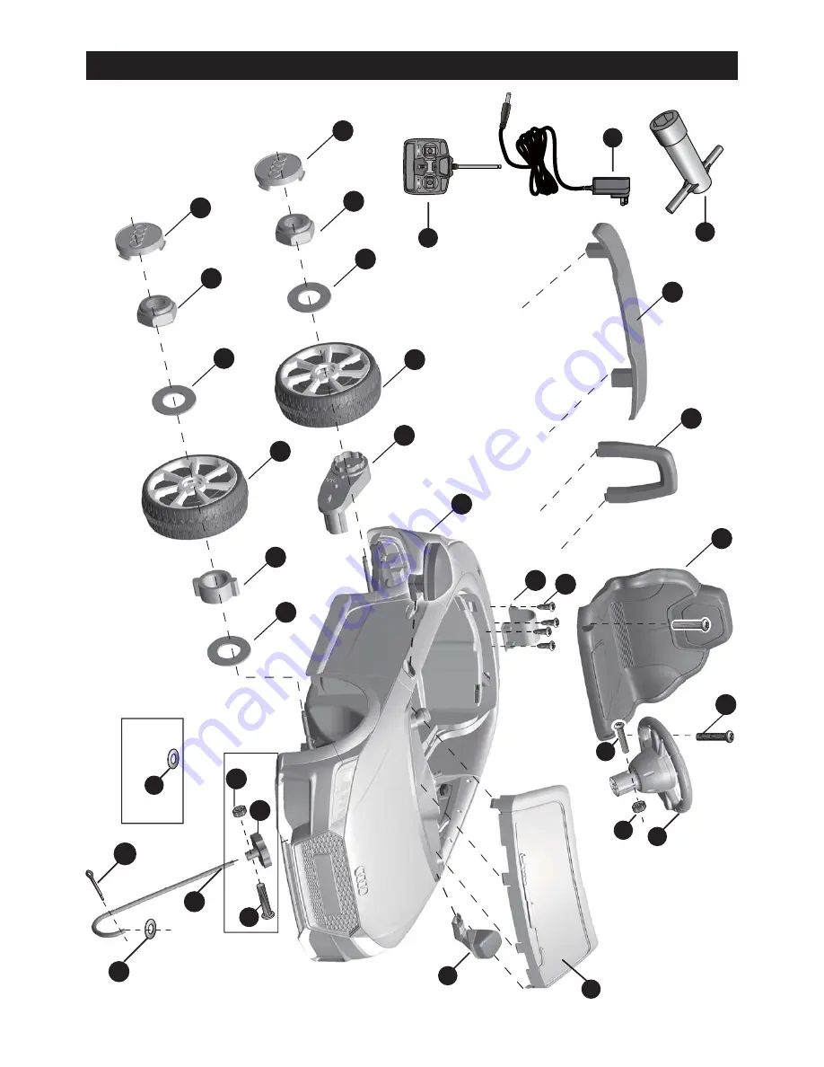
Parts Diagram   

  3

HINT: Some parts shown are assembled on both sides of vehicle

CONTROLLER STYLES MAY VERY

R/C Type

Normal Type

Summary of Contents for AUDI TT RS

Page 1: ...he owner s manual contains important safety information as well as assembly use and maintenance instructions The Ride on Car must be assembled by an adult who has read and understands the instructions in this manual Keep the package away from children and dispose of properly before use Keep this manual for future reference ...

Page 2: ...it s rider Battery Charger 6V4 AH 1 6V7Ah 1 or 6V10 1 6V500mA or 6V1000mA 6V4Ah 2 or 6V7Ah 2 12V1000mA Suitable age Load Capacity Speed Size of car Power way Charge time 37 96 Months Under 30 kgs 1WD 2 5 km h 2WD 2 5 5 km h 103 x 62 x 43 5 CM Charging type 8 12 hours About Your New Ride On 1 VER SMS JE1198 TT RS EN 170520 Audi TT RS Electric Ride on manufactured by Zhejiang Jiajia Ride on Co Ltd A...

Page 3: ...t head screw Lock nut Hubcap Steering column Windshield Mirror Steering Wheel M5x35 machine screw Ø5 nut Seat M5x16 machine screw Seat rest Rear spolier Split pin Charger Spanner Remote controller Ø5 nut R C driver M5x22 machine screw Placed on the steering wheel Placed on the steering wheel Left and right One labeled L and the other one labeled R 1WD 2WD 2WD Parts List 2 IF EQUIPPED for R C type ...

Page 4: ...6 22 23 24 13 14 1 7 3 2 5 6 6 9 10 6 9 10 20 19 17 18 4 8 12 11 21 6 26 25 27 6 Parts Diagram 3 HINT Some parts shown are assembled on both sides of vehicle CONTROLLER STYLES MAY VERY R C Type Normal Type ...

Page 5: ...eing charged Rechargeable batteries are only to be charged under adult supervision Different types of batteries or new and used batteries are not to be mixed Batteries are to be inserted with the correct polarity Exhausted batteries are to be removed from the toy The supply terminals are not to be short circuited BATTERY INFORMATION CHOKING HAZARD Small parts Not suitable for children under 36 mon...

Page 6: ...h the gear box 3 Slide the Ø10 Washer onto the rear axle 4 Tighten a Lock nut to the end of the rear axle with a spanner 5 Slide the Ø10 Washer onto the rear axle Right Side 6 Insert the bush into the hole in the center of the normal wheel 7 Slide the Normal wheel onto the rear axle 8 Slide the Ø10 Washer onto the rear axle 9 Tighten a Lock nut to the end of the rear axle with a spanner HINT An ex...

Page 7: ...connector on the gear box through the larger hole on the rear vehicle and out where the battery sits 2 Slide the driving wheel onto the rear axle And keep the driving wheel match with the gear box 3 Slide the Ø10 Washer onto the rear axle 4 Tighten a Lock nut to the end of the rear axle with a spanner Repeat the above procedure to assemble the other driving wheel HINT An extra spanner has been pro...

Page 8: ...t axle 2 Slide a bush into the hole in the center of the normal wheel 3 Slide the normal wheel onto the rear axle And keep the normal wheel match with the bush 4 Slide a Ø10 washer onto the front axle 5 Tighten a Lock nut to the end of the front axle with a spanner 6 Snap the hubcap to the wheel Repeat the above procedure to assemble the other front wheel ...

Page 9: ...the screw to secure the steering wheel to the steering column 1 With a screwdriver remove the screw on the battery cover located in the center of the steering wheel 2 Remove the battery cover from the top of the battery compartment 3 Insert two AA batteries in their correct polarities 4 Place the battery cover over the battery compartment and fasten with the screw you removed in step one Attache t...

Page 10: ...t the straight end of steering column up through the hole in the front of vehicle body from bottom side and out through the hole in the dash 3 Insert the bent end of steering column through the hole in the front axle linkage 4 Fit a Ø10 washer onto the bent end of the steering column 5 Insert a split pin into the hole in the steering column bend the ends of split pin back using a long nose pliers ...

Page 11: ...umn up through the hole in the R C driver the hole in the steering gear box from the bottom side and out through the hole in the dash 3 Line up the holes in the R C driver and the hole in the steering column tighten a M5x22 machine screw and Ø5 nut back in the same location with a screwdriver 4 Insert the bent end of steering column through the hole in the front axle linkage 5 Fit a Ø10 washer to ...

Page 12: ...y as shown above 2 Plug the Red fuse connector into the terminal on battery 1 Plug the Vehicle Connector into the Motor Connector on body as shown above Repeat for the other side 2 Plug the Red fuse connector into the terminal on battery Rear Top View Fuse box Battery Vehicle connector Motor connector ...

Page 13: ... 12 1WD 2WD 1 Fit the motor hood on the motor 2 Tighten four Ø4x12 flat head screws to secure it 1 Fit the motor hood on the motor 2 Tighten four Ø4x12 flat head screws to secure it Repeat the above steps for the other Motor hood ...

Page 14: ...it the tabs on the back of seat into the slots on the rear vehicle 2 Tighten two M5x16 machine screws to secure it with a screwdriver 3 Fit the tabs on the windshiled into the slots on the front vehicle and push until you hear it click into place ...

Page 15: ... Rest Rear Spolier 14 1 Fit the tabs on the mirror into the hole on the vehicle side push until you hear click into place Repeat for the other side 2 Fit the seat rest to the rear vehicle 3 Fit the rear spolier to the rear vehicle ...

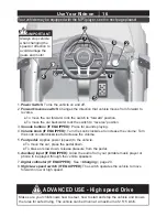
Page 16: ...ding This vehicle has adjustable play seat belts Please instruct children how to tie the safety belt before using guarantee the security Keep Children within Safe Riding Areas Never use in roadway near motor vehicles on lawn space on or near steep inclines or steps swimming pools or other bodies of water Use the toy only on flat surfaces Such as inside your house garden or playground Never use in ...

Page 17: ...IF EQUIPPED Turn the knob clockwise to increase the volume Turn the knob counterclockwise to decrease the volume 5 Foot pedal Applies power speed to the vehicle To move the car press the pedal down To brake or slow down release pressure from the pedal 6 Auxiliary input IF EQUIPPED Allow the audio from your portable music player or phone to be played through the vehicle speakers 7 Digital voltmeter...

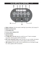
Page 18: ...mode E Increase volume F Decrease volume G TF Micro SD card slot Allow the audio from your TF card to be played through the vehicle speakers MP3 format ONLY H MP3 audio input AUX input Allow the audio from your portable music player or phone to be played through the vehicle speakers MP3 format ONLY I USB interface Allow the audio from your portable device to be played through the vehicle speakers ...

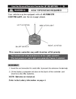
Page 19: ... information on page 4 ON OFF SWITCH INDICATOR LIGHT RIGHT JOYSTICK LEFT JOYSTICK Use the Normal Remote Controller IF EQUIPPED 18 ADULT OPERATING REQUIRED WARNING The remote control has precedence over foot pedal operation The foot pedal won t work while you operate the Remote Controller Your vehicle may be equipped with a 2 4G REMOTE CONTROLLER see the next page please This remote controller may ...

Page 20: ...operates the vehicle to move in low normal or high speed HINT The vehicle is designed to operate in low speed only in reverse Leave the remote controller idling for about 10 seconds it will shut down automatically Repeat step 1 when you replace the batteries of the remote controller Connection button Forward button Left turning button Right turning button Brake button Speed select button High spee...

Page 21: ...Use the Door Lock 20 Door inside Door Lock NOTE Please close the door and ensure the lock snap into place when riding for safety consideration ...

Page 22: ...rnia to cause cancer and reproductive harm Wash hands after handling Do not open the battery Battery contains lead acid and other materials that are toxic and corrosive Do not open the charger Exposed wiring and circuitry inside case may cause electric shock Only adults may handle or charge the battery NEVER allow child to handle or charge the battery Battery is heavy and contains lead acid electr...

Page 23: ...k normally STOP operating the vehicle the battery needs to be charge 1 Plug the charger port into the input socket the socket is below the seat HINT If your vehicle equipped with the Multi function Dash the Charging Socket is on the dash please see page 15 Use the Multi function Dash 2 Plug the charger plug into a wall outlet The battery will begin charging WARNING This product with Charging Prote...

Page 24: ...nd Disposal The battery will eventually lose the ability to hold a charge Depending on the amount of use and varying conditions the battery should operate for one to three years Follow these steps to replace and dispose the battery 1 Remove the car seat 2 Disconnect the battery connectors 3 Remove the battery bracket 4 Remove the battery cover 5 Carefully lift the battery Depending on the conditio...

Page 25: ... connection and the vehicle needs repair Contact your distributor please Attempting to shift while the vehicle is motion Completely stop the vehicle and shift see Use Your Ride On Check that the battery connectors are firmly plugged into each other when recharging Replace battery contact your distributor please Replace battery contact your distributor please Replace battery contact your distributo...

Page 26: ...s and heaters Plastic parts may melt Recharge the battery after each use Only an adult can handle the battery Recharge the battery at least once a month when the vehicle Raider is not being used Do not wash the vehicle with a hose Do not wash the vehicle with soap and water Do not drive the vehicle in rainy or snowy weather Water will damage the motor electric system and battery Clean the vehicle ...

Page 27: ...Our products are suitable for ASTM F963 GB6675 EN71 and EN62115 standard Importer Tigris Unit Micheldever Hampshire SO21 Model AUDITT Code 3AJ Farm Northbrook 1 Limited Wholesale International ...

Reviews: