background image


Zhone Technologies, Inc.  @Zhone Way,  7001 Oakport St.,  Oakland, CA 94621   (510) 777-7000  Fax: (510) 777-7001 


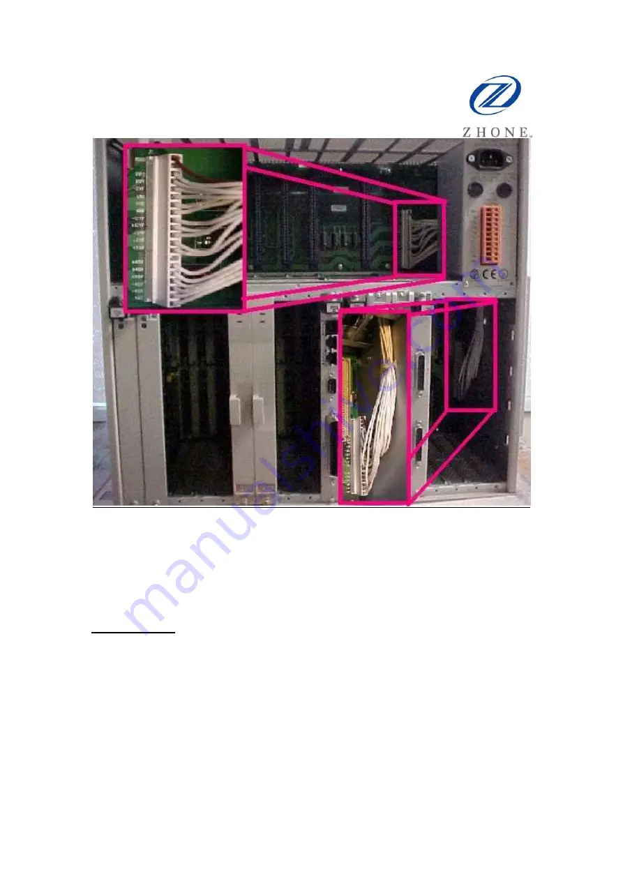
Figure 2: IMACS-900 Power Cable Location 

 
The Power Supply cable is located on the front of the IMACS-900 and extends between 
the top power supply portion of the shelf behind slot F2 and the lower shelf backplane 
behind circuit card slot U8.  
 
Note that the brown wire of the cable is oriented to the top of the cable connector. 
 
Cable Removal: 
In order to remove the cable, it will be necessary to remove power from the shelf. Prior to 
starting, it should be recorded what cards occupy which slots. It is highly recommended 
to perform a database backup prior to beginning the procedure (save to flash, save off-
shelf). In order to have room to maneuver, it is recommended that the cards around the 
cable connector be removed to allow for plenty of room to work on the shelf. 
 
Procedurally: 

1.


Back up system image to flash. On the main login screen, enter ‘Y’ for 
system. Select ‘B’ for backup, and change ‘PROTOCOL’ from ASCII to 

Summary of Contents for 900

Page 1: ...required on an IMACS 600 or IMACS 800 shelf The IMACS 900 uses a 18 pin wiring harness to connect the power PCB to the shelf PCB The cable is shown in Figure 1 Figure 1 Power Cable IMACS 900 This procedure is provided to augment the Field Advisory bulletin 20071206 2 FAB IMACS Power Supply OOS Alarm This Tech Tip provides greater detail on the item under the section for Valid Alarms of that bullet...

Page 2: ...to clean the power supply cable is for the IMACS 900 shelf It is suggested that this procedure be performed on any IMACS shelf over ten years old at the same time as the Interface card battery replacement To find out more about the Interface card battery replacement call your Zhone representative and ask about GSS service product codes 3021AR and 3021FG This power cable maintenance procedure can b...

Page 3: ...f the cable connector Cable Removal In order to remove the cable it will be necessary to remove power from the shelf Prior to starting it should be recorded what cards occupy which slots It is highly recommended to perform a database backup prior to beginning the procedure save to flash save off shelf In order to have room to maneuver it is recommended that the cards around the cable connector be ...

Page 4: ...p to the elbow 5 Remove power supply cover from the front of the shelf 6 Record circuit pack locations refer to Table 1 7 Remove circuit packs around the work area to allow for maneuvering 8 Remove the power cable 9 Clean the power cable 10 Clean the posts 11 Replace the IF card battery on shelves nine years old or older 12 Replace the power cable 13 Replace the circuit packs 14 Reconnect power to...

Page 5: ...s The removal of the power block will reveal the locations of the tie wraps which must be cut in order to allow for the removal of the power cable Refer to figure 4 below to identify the locations to cut the tie wrap holders Use extreme caution when cutting these tie wraps to ensure that the power cable is not accidentally damaged ...

Page 6: ...nce the tie wraps have been cut and removed the power cable can then be removed from the shelf by threading the cable through the slot to the right of location U8 The cable is held in place by locking edges on the connector and the mating connector housing This mechanism is used to securely hold the cable to the motherboard see Figure 5 below ...

Page 7: ...he posts on the IMACS backplanes should also be cleaned with the degreaser used above A non conductive oxidation preventative should be rubbed onto the metal posts to ensure complete coverage and coating Cable Replacement Once the cable and posts have been thoroughly cleaned and coated the cable can then be replaced When re installing the cable ensure that the brown wire is oriented towards the to...

Page 8: ...placed back into its original location as illustrated in Figures 2 and 3 With the power properly routed the individual cards should be replaced as documented in Table 1 Care should be taken to properly secure each card into its respective slot in accordance with the recorded data Validation With all the cards now firmly in place the unit is ready for power to be applied Reconnect the power source ...

Reviews: