Configuring Bridging
86
EtherXtend User’s Guide
Broadcasts and bridging
The EtherXtend supports a modified form of broadcast suppression when
configured for bridge mode. The EtherXtend configures ports as the entered
bridge type.
In general, broadcasts sent to a downlink will traverse the uplink, but will not
be sent down other downlinks, even within the same VLAN. This prevents
subscribers from maliciously or unintentionally sending or receiving
broadcasts between ports on the same system.
Ports configured as uplinks will send broadcasts upstream, but by default will
not propagate broadcasts sent from the upstream down to the EtherXtend. The
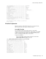
filterBroadcast parameter in the bridge-interface-record profile enables this
filtering. This mechanism provides security benefits, as well as reducing
unnecessary traffic on low bandwidth interfaces.
One exception to the operational mode described above is ARP broadcast
support. When a EtherXtend receives a broadcast frame, it is checked to
determine if it is an ARP protocol packet or not. If it is not, it is treated as
above. If it is, then the EtherXtend compares and filters the requested IP
address with the current forwarding table. If a match is found, the ARP
broadcast is forwarded out the interface that has the appropriate host. This
host will then reply to the ARP with a standard response. If a match is not
found, then the ARP is filtered and it gets dropped as if it were a non-ARP
broadcast. This setting is controlled by the customARP parameter.
Another exception to this broadcast filtering is DHCP broadcast support.
When a EtherXtend receives a broadcast DHCP OFFER message from a
remote DHCP server, if customDHCP is set to true, the broadcast messages
are forwarded to the source MAC address. Otherwise, the broadcast DHCP
messages are filtered.
Note:
Ethernet interfaces can be addressed as either
eth
or
ethernetcsmacd
. The
eth
abbreviation is used in command output.
VLANs
shows a typical VLAN configuration. On the access (subscriber)
side, VLANs 1 and 2 are separate DSL networks connected to the EtherXtend
via EtherXtend devices. On the uplink side, VLANs 1 and 2 are on the same
physical Ethernet interface, but the traffic is separated based on the VLAN
IDs.
The side of the connection closest to the subscriber is called the downlink
interface. The upstream egress is called the uplink interface. When the
EtherXtend is in VLAN mode, it adds (tags) the VLAN ID to the Ethernet
frame on the uplink interface and strips (untags) the ID out on the downlink
interface. Although VLAN IDs are not typically required on downlink
interfaces, you can configure the downlink interface as tagged. Tagged
Summary of Contents for EtherXtend 3300 Series
Page 8: ...Contents 6 EtherXtend User s Guide...
Page 18: ...Overview 16 EtherXtend User s Guide...
Page 70: ...Basic Configuration 68 EtherXtend User s Guide...
Page 132: ...Advanced Configuration 130 EtherXtend User s Guide...
Page 146: ...IP Service Level Agreement 144 EtherXtend User s Guide...
Page 150: ...Index 148 EtherXtend User s Guide...

