9-6
High Speed Data Ports
Model No.
Running Head
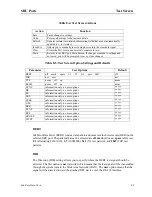
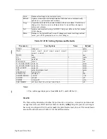
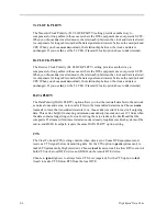
Tx CLOCK PLRTY
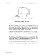
The Transmit Clock Polarity (Tx CLOCK PLRTY) setting provides another way to
compensate for long cables in those cases where the DTE equipment does not provide SCTE.
When you choose inv (inverted mode), the relationship between the clock and data is altered
to compensate for long cable runs that the data signals must traverse between the card port and
CPE. When you choose norm (normal), the relationship between the clock and data is
unchanged. If you use inv, set the Tx CLK (Transmit Clock) option above to int (internal).
Rx CLOCK PLRTY
The Receive Clock Polarity (Rx CLOCK PLRTY) setting provides another way to
compensate for long cables in those cases where the DTE equipment does not provide SCTE.
When you choose inv (inverted mode), the relationship between the clock and data is altered
to compensate for long cable runs that the data signals must traverse between the card port and
CPE. When you choose norm (normal), the relationship between the clock and data is
unchanged. If you use inv, set the Tx CLK (Transmit Clock) option above to int (internal).
DATA PLRTY
The Data Polarity (DATA PLRTY) option allows you to either send all data bits to the network
as normal ones and zeros, or to invert all bits in the transmitted data stream. Choose norm
(normal) to leave the transmitted data intact; or, choose inv (inverted) to invert all outgoing
data. This can be helpful in ensuring minimum-ones density transmission over T1 links when
the data contains long strings of zeros. Inverting the zeros reduces the likelihood that the
composite T1 stream will not meet minimum-ones density requirements. Both systems of the
end-to-end HSD circuit path require the same DATA PLRTY option setting.
CTS
The Clear To Send (CTS) setting controls when data is sent. Some DTE equipment must
receive a CTS signal before transmitting data. Set the CTS option to perm (permanent) to
make CTS permanently High (asserted). Choose rlocal (remote-local) to allow RTS to control
both CTS on the local DTE device and RLSD on the remote DTE device.
Choose to ignor (ignore) to always force CTS Low (negated). Set the CTS option to locl
(local) to make CTS follow RTS from the local DTE.
Summary of Contents for IMA CS-200 System
Page 18: ...8 Table of Contents Model No Running Head Table of Contents...
Page 22: ...4 List of Figures Model No Running Head List of Figures...
Page 130: ...4 46 General Features Model No Running Head CPU Troubleshooting IMACS 200 General Features...
Page 148: ...5 18 WAN Ports Model No Running Head WAN port Troubleshooting WAN ports...
Page 202: ...9 14 High Speed Data Ports Model No Running Head...
Page 208: ...10 6 OHSU Ports Model No Running Head...
Page 230: ...12 16 IPR Model No Running Head IPR Configuration Screens and Settings IP Routing...
Page 264: ...A 12 System Standards and Specifications Model No Running Head IPR Server Specifications...
Page 274: ...B 10 Error Messages Model No Running Head...
Page 294: ...20 Glossary Model No Running Head Zero Code Suppression...

