OHSU Ports
10-5
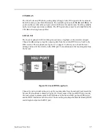
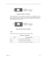
Figure 10-4.Local User Loopback
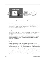
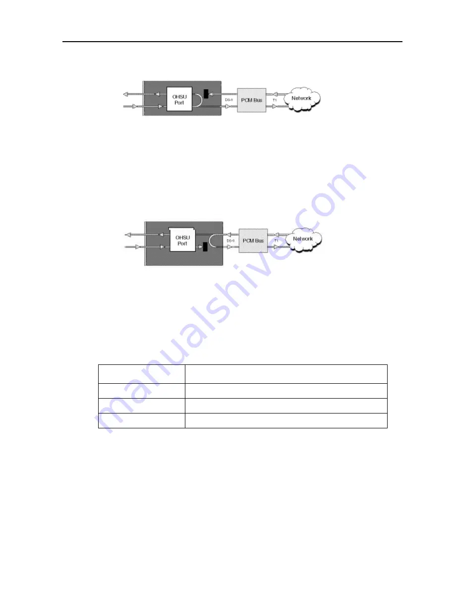
Choose the net (network) setting to loop the incoming data from the network back toward the
far end. This loopback is shown in Figure 10-5. It tests some of the local OHSU port circuitry,
the local system common ports, the WAN link port, the far-end OHSU port and CPE device,
and the WAN link between the two sites.
Figure 10-5.Local Network Loopback
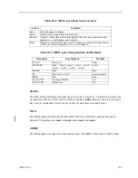
Alarm
The alarm field is an indication field that shows the optical link status.
Table 10-3. Alarm Field
Field
Optical Link Status
Norm
The optical link is operating properly.
Yellow
The TPE is reporting a reception fault.
Red
The OHSU port is reporting a reception fault.
Summary of Contents for IMA CS-200 System
Page 18: ...8 Table of Contents Model No Running Head Table of Contents...
Page 22: ...4 List of Figures Model No Running Head List of Figures...
Page 130: ...4 46 General Features Model No Running Head CPU Troubleshooting IMACS 200 General Features...
Page 148: ...5 18 WAN Ports Model No Running Head WAN port Troubleshooting WAN ports...
Page 202: ...9 14 High Speed Data Ports Model No Running Head...
Page 208: ...10 6 OHSU Ports Model No Running Head...
Page 230: ...12 16 IPR Model No Running Head IPR Configuration Screens and Settings IP Routing...
Page 264: ...A 12 System Standards and Specifications Model No Running Head IPR Server Specifications...
Page 274: ...B 10 Error Messages Model No Running Head...
Page 294: ...20 Glossary Model No Running Head Zero Code Suppression...

