


A-6
System Standards and Specifications
Model No.
Running Head
A.4.3
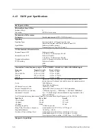
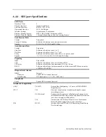
E&M port Specifications
E&M ports 4-Wire
Physical Interface 4-Wire
Number of Ports
4
Connectors
4 RJ45 telco connector
Transmission Performance
Performance
Exceeds requirements of ITU-T G.712 (4-wire))
Signaling
Signaling Types
Switch selectable - all four ports are the same
Normal (toward user) and Trunk/Tandem (toward CO)
Signal Modes
Software selectable per port
Transmit Only (to), Type I, II, IV and V.
VF Transmission Characteristics
Nominal Transmit TLP
Software selectable
-16.5 dB to +7.5 dB in steps of 0.1 dB
Nominal Receive TLP
Software selectable
-16.3 dB to +7.5 dB in steps of 0.1 dB
Termination Impedance
with 2.16
µ
f capacitor in series 600 Ohms
PCM Encoding
Software selectable
µ
-law
A-law
Attenuation Versus Frequency as per AT&T TR43801 - Relative to 1 kHz with 0 dBm0 input
Frequency
Transmit (A to D)
Receive (D to A)
200 Hz
-0.25 to +3.0 dB
-0.25 to +2.0 dB
300 to 3000 Hz
-0.25 to +0.5 dB
-0.25 to +0.5 dB
3200 Hz
0.25 to +0.75 dB
-0.25 to +0.75 dB
3400 Hz
-0.25 to +1.5 dB
-0.25 to +1.5 dB
Return Loss
Against 600 Ohms, in series with 2.6
µ
f with additional 25 Ohms
resistor between the channel unit and the return loss measurement set.
4-wire
1kHz 28dB min.
300 to 3000 Hz 23dB min.
4W Return Loss (at 1 kHz)
>20dB Typ > 27dB
Relative Transhybrid Loss
Against 600 Ohms, in series with 2.16
µ
f termination.
Idle Channel Noise (rcv and xmt)
< -65Bm0p. Typically < -70 dBm0p or < 20 dBrnc0 <20dBBrnc0
Interchannel Crosstalk
Typ < -75 dBm0 using 7 adjacent channels being distributed with a
signal of 0.0 dBm0.
Total Distortion including Quantization (Signal to Distortion Ratio) Input Frequencies 1004-1020 Hz
Input Level
Rcv or Xmt
Overall
-30 to 0 dBm0
>35 dB
>33.9 dB
-40 dBm0
>20 dB
>27.6 dB
-45 dBm0
>25dB
>23 dB
Absolute group delay
< 600 microseconds
Group Delay Distortion vs. frequency
within boundaries of ITU-T Rec. G.712 Figure 2
Longitudinal Balance
>46 dB Typ > 50 dB
Variation of Gain with Input Level
within boundaries of ITU-T Rec. G.713 Figure 7 (2 wire)
within boundaries of ITU-T Rec. G.712 Figure 7 (4 wire)
Typical gain variation is 0.25 dB from +3 to -50 dBm0
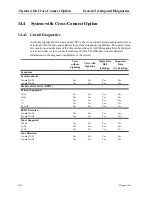
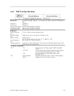
Diagnostic Capabilities
Summary of Contents for IMA CS-200 System
Page 18: ...8 Table of Contents Model No Running Head Table of Contents...
Page 22: ...4 List of Figures Model No Running Head List of Figures...
Page 130: ...4 46 General Features Model No Running Head CPU Troubleshooting IMACS 200 General Features...
Page 148: ...5 18 WAN Ports Model No Running Head WAN port Troubleshooting WAN ports...
Page 202: ...9 14 High Speed Data Ports Model No Running Head...
Page 208: ...10 6 OHSU Ports Model No Running Head...
Page 230: ...12 16 IPR Model No Running Head IPR Configuration Screens and Settings IP Routing...
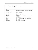
Page 264: ...A 12 System Standards and Specifications Model No Running Head IPR Server Specifications...
Page 274: ...B 10 Error Messages Model No Running Head...
Page 294: ...20 Glossary Model No Running Head Zero Code Suppression...