


System Standards and Specifications
A-9
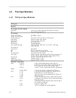
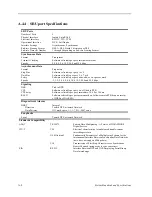
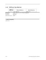
A.4.5
HSU Port Specifications
Number of
Data Ports
Physical Interfaces
Electrical Interfaces
2
2 female 25-pin DB25 D-connectors
ITU-T V.35
Data Speeds
N x 56k and N x 64k, where N = 1 to 24 (up to 1536 kbps) - Software Configurable by
DS0
Data Format
Synchronous
Data Protocol
Transparent
Transmit Clock per Port
Internal or External (software selectable)
Clock Polarity per Port
Normal or inverted (software selectable)
Data Polarity per Port
Normal or inverted (software selectable)
Diagnostics
RTS/CTS Delay: per
Port
0, 30, 60 or 100 ms (software selectable by port)
RTS Handshake per
Port
Permanent, local, ignore, local (software selectable by port)
BER Test per Port
Active or inactive
BER Test Patterns All Marks, All Spaces, 1:1, 1:7, QRSS, 511, 2047
Local Loopback per
Port
None, towards DTE, towards the network
Performance Statistics
Errored Seconds, Unavailable Second, Severely Errored Second, Burst Errored Second, Loss of
Packet Seconds, Loss of Frame Count
Standards Compatibility
ITU-T
V.35
V.11 (10/96)
V.28
Data Transmission of 48 kbps using 60-108 kHz Group Bank
Circuits.
Electrical characteristics for balanced double-current interchange
circuits operating at data signaling rates up to 10 Mbit/s.
Electrical characteristics for unbalanced double-current
interchange circuits.
EIA
Recommendations
RS-530
High Speed 25 Position Interface for Data Terminal Equipment,
Including Alternative 25 Position Connector.
Summary of Contents for IMA CS-200 System
Page 18: ...8 Table of Contents Model No Running Head Table of Contents...
Page 22: ...4 List of Figures Model No Running Head List of Figures...
Page 130: ...4 46 General Features Model No Running Head CPU Troubleshooting IMACS 200 General Features...
Page 148: ...5 18 WAN Ports Model No Running Head WAN port Troubleshooting WAN ports...
Page 202: ...9 14 High Speed Data Ports Model No Running Head...
Page 208: ...10 6 OHSU Ports Model No Running Head...
Page 230: ...12 16 IPR Model No Running Head IPR Configuration Screens and Settings IP Routing...
Page 264: ...A 12 System Standards and Specifications Model No Running Head IPR Server Specifications...
Page 274: ...B 10 Error Messages Model No Running Head...
Page 294: ...20 Glossary Model No Running Head Zero Code Suppression...