


System Installation
2-5
System Installation
Connector Types
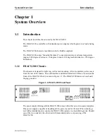
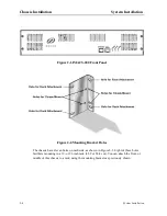
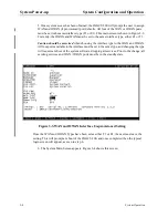
Figure 2-3.Chassis Mounting Holes
Table 2-1 outlines the minimum clearance that is recommended for the IMACS-200 on all four
sides.
Table 2-1. Minimum Chassis Clearances
2.3
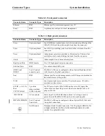
Connector Types
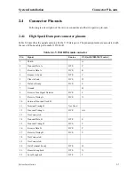
The product is equipped with several types of electrical connections to the network and power
sources. Table 2-2 lists the connections on the front panel of the IMACS-200 (Refer to Figure
2-1 on page 2-4 for an illustration of the IMACS-200 front panel). These connections are
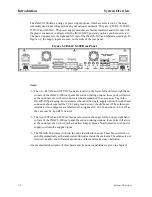
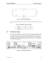
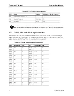
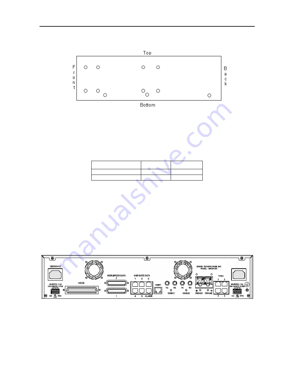
available for the crafts person to gain easy access into the unit. Table 2-3 lists the back panel
connectors along with their functionality. (Refer to Figure 2-4 on page 2-5 for an illustration
of the IMACS-200 back panel)
Figure 2-4. IMACS-200 Rear Panel
Clearance
Front
Rear
Inches
10
10
Centimeters
25
25
Summary of Contents for IMA CS-200 System
Page 18: ...8 Table of Contents Model No Running Head Table of Contents...
Page 22: ...4 List of Figures Model No Running Head List of Figures...
Page 130: ...4 46 General Features Model No Running Head CPU Troubleshooting IMACS 200 General Features...
Page 148: ...5 18 WAN Ports Model No Running Head WAN port Troubleshooting WAN ports...
Page 202: ...9 14 High Speed Data Ports Model No Running Head...
Page 208: ...10 6 OHSU Ports Model No Running Head...
Page 230: ...12 16 IPR Model No Running Head IPR Configuration Screens and Settings IP Routing...
Page 264: ...A 12 System Standards and Specifications Model No Running Head IPR Server Specifications...
Page 274: ...B 10 Error Messages Model No Running Head...
Page 294: ...20 Glossary Model No Running Head Zero Code Suppression...


