


2-8
System Installation
Model No.
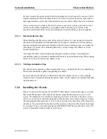
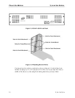
Running Head
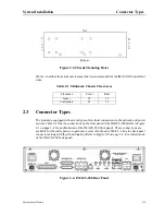
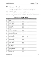
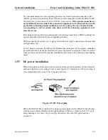
Connector Pin-outs
System Installation
Note:
For purposes of connection and function, the IMACS-200 should be considered a DCE.
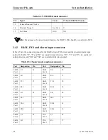
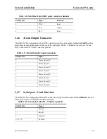
2.4.2
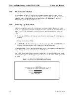
E&M, FXS and Alarm input connector
Table 2-5 lists the connector pinouts for the E&M circuits, FXS circuit and the provided alarm input
points. For E&M, “R”, “T” and “M” are consider input direction, “R1”, “T1” and “E” are considered
output direction, and “SB” and “SG” are considered direction-neutral.
23
External Transmit Clock A
24
Terminal Timing A
Not Used
U
25
Test Mode
DCE
NN
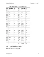
Table 2-5. 25-pair female amphenol connector
Port
Designation
Pin
Port
Designation
Pin
E&M
Port 1
T-1
26
E&M
Port 4
T-4
38
E&M
Port1
R-1
1
E&M
Port4
R-4
13
E&M
Port 1
T1-1
27
E&M
Port 4
T1-4
39
E&M
Port 1
R1-1
2
E&M
Port 4
R1-4
14
E&M
Port 1
E-1
28
E&M
Port 4
E-4
40
E&M
Port 1
M-1
3
E&M
Port 4
M-4
15
E&M
Port 1
SG-1
29
E&M
Port 4
SG-4
41
E&M
Port 1
SB-1
4
E&M
Port 4
SB-4
16
E&M
Port 2
T-2
30
FXS
Port 1
T-1
42
E&M
Port 2
R-2
5
FXS
Port 1
R-1
17
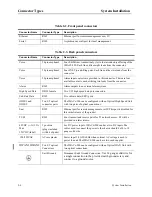
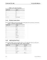
Table 2-4. V.35 DB25 female connector
Pin
Signal
Source
V.35 (with PRM-1261F cable)
Summary of Contents for IMA CS-200 System
Page 18: ...8 Table of Contents Model No Running Head Table of Contents...
Page 22: ...4 List of Figures Model No Running Head List of Figures...
Page 130: ...4 46 General Features Model No Running Head CPU Troubleshooting IMACS 200 General Features...
Page 148: ...5 18 WAN Ports Model No Running Head WAN port Troubleshooting WAN ports...
Page 202: ...9 14 High Speed Data Ports Model No Running Head...
Page 208: ...10 6 OHSU Ports Model No Running Head...
Page 230: ...12 16 IPR Model No Running Head IPR Configuration Screens and Settings IP Routing...
Page 264: ...A 12 System Standards and Specifications Model No Running Head IPR Server Specifications...
Page 274: ...B 10 Error Messages Model No Running Head...
Page 294: ...20 Glossary Model No Running Head Zero Code Suppression...


