


2-10
System Installation
Model No.
Running Head
Connector Pin-outs
System Installation
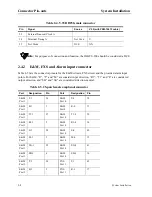
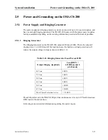
2.4.4
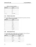
Ethernet connections
Table 2-7 lists the RJ45 connector pinouts for the ethernet ports on the front and rear of the chassis.
2.4.5
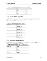
Sub Rate Data Ports
Table 2-8 lists the RJ45 connector pinouts for the five sub rate data ports on the rear of the chassis.
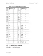
Table 2-6. T1 connector pinouts
RJ-45(F) Pin
Signal
1
R1
2
T1
4
R
5
T
3, 6, 7, 8
Not assigned
Table 2-7. Ethernet connector pinouts
RJ-45(F) Pin
Signal
1
TXP
2
TXN
3
RXP
4
TXCT
5
RXCT
6
RXN
7
Not used
8
Ground
Table 2-8. Sub Rate Data (SRU) ports connector pinouts
RJ-45(F) Pin
Signal
Direction
1
SCT
Output
2
RLSD
Output
3
SCR
Output
4
Ground
5
RXD
Output
Summary of Contents for IMA CS-200 System
Page 18: ...8 Table of Contents Model No Running Head Table of Contents...
Page 22: ...4 List of Figures Model No Running Head List of Figures...
Page 130: ...4 46 General Features Model No Running Head CPU Troubleshooting IMACS 200 General Features...
Page 148: ...5 18 WAN Ports Model No Running Head WAN port Troubleshooting WAN ports...
Page 202: ...9 14 High Speed Data Ports Model No Running Head...
Page 208: ...10 6 OHSU Ports Model No Running Head...
Page 230: ...12 16 IPR Model No Running Head IPR Configuration Screens and Settings IP Routing...
Page 264: ...A 12 System Standards and Specifications Model No Running Head IPR Server Specifications...
Page 274: ...B 10 Error Messages Model No Running Head...
Page 294: ...20 Glossary Model No Running Head Zero Code Suppression...


