2-14
System Installation
Model No.
Running Head
Power and Grounding on the IMACS-200
System Installation
2.5.2
System Power (Redundancy)
The IMACS-200 provides power redundancy for any of the powering options. The supplies
are factory-installed, and the external connectors to receive the powering options selected will
be pre-installed on the unit. Figure 2-4 on page 2-5 high-lites the location of the Power Supply
feeds.The 120VAC and 220VAC power inputs are lightly shaded, and the -48VDC and
125VDC options are darkly shaded.
2.5.3
AC Power Supply and DC Power Supply Fuses
The AC power supply and DC Power Supply fuses are already built in to the supplies. These
fuses are not field serviceable. When unpacking the unit, an AC power cord will be in the box
for each of the AC power supplies ordered. The AC inlet connector is located in the rear
corners of the chassis. For a single supplied unit, the rear right-hand connector will be
equipped. Refer to the system specifications section in this manual for input power
requirements.
2.5.4
System Power and Ground Connections
After installing the system, make the power and ground connections to the chassis as
described in this section. A frame ground connection is provided in the right-rear corner of the
IMACS-200 rear panel.
2.5.5
Grounding requirements
Due to the UL regulatory requirements, a mounting stud is required for connection of the AC
input earth ground lead to the product chassis. The ground lead must be connected to the
chassis using a No. 6 screw, which is included. When grounding the system, use 14 gauge
solid wire for a single connection to the provided earth ground screw. The mounting location
is labeled with the IEC 417 No. 5019 symbol to identify this as the AC earth ground
connection point. This mounting stud is located next to the IEC 320 AC input connector.
2.5.6
Chassis with Power Supplies
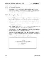
Figure 2-4 on page 2-5 shows the different power connections on the chassis.
For DC powered systems, the lower right and lower left-hand connections provide for
separate, redundant power feeds to the system's pre-installed DC power supplies if so
equipped. These two sets of leads provide a connection for separate, redundant power feeds
to the system in a load-sharing mode.
Summary of Contents for IMA CS-200 System
Page 18: ...8 Table of Contents Model No Running Head Table of Contents...
Page 22: ...4 List of Figures Model No Running Head List of Figures...
Page 130: ...4 46 General Features Model No Running Head CPU Troubleshooting IMACS 200 General Features...
Page 148: ...5 18 WAN Ports Model No Running Head WAN port Troubleshooting WAN ports...
Page 202: ...9 14 High Speed Data Ports Model No Running Head...
Page 208: ...10 6 OHSU Ports Model No Running Head...
Page 230: ...12 16 IPR Model No Running Head IPR Configuration Screens and Settings IP Routing...
Page 264: ...A 12 System Standards and Specifications Model No Running Head IPR Server Specifications...
Page 274: ...B 10 Error Messages Model No Running Head...
Page 294: ...20 Glossary Model No Running Head Zero Code Suppression...

