3-2
System Operation
Model No.
Running Head
System Power-up
System Configuration and Operation
3.3.1
System Boot
Following the application of power, proceed as follows:
1. Be sure your system and local terminal are both powered up.
2. Connect a VT100-compatible terminal to the SERIAL jack on the faceplate of the
IMACS-200 front panel. Use a cable with an RJ-45 modular plug on one end for this
connection.
3. Configure the terminal to operate at 9.6 kbps, 8 data bits, no parity, and 1 stop bit.
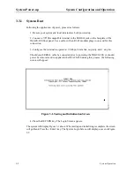
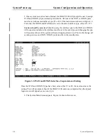
Should your SERIAL cable be connected prior to powering the IMACS-200, or should
power be removed and re-applied to the IMACS-200 during this process, the following
screen will appear:
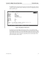
Figure 3-1.Testing and Initialization Screen
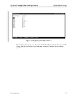
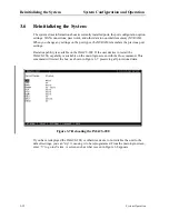
4. Press the RETURN key. The Login Screen appears.
The system will display Figure 3-1 above. When testing and initializing is complete the screen
will go blank. Press the <Enter> key. The System Login Screen will display, as seen in Figure
3-2
Summary of Contents for IMA CS-200 System
Page 18: ...8 Table of Contents Model No Running Head Table of Contents...
Page 22: ...4 List of Figures Model No Running Head List of Figures...
Page 130: ...4 46 General Features Model No Running Head CPU Troubleshooting IMACS 200 General Features...
Page 148: ...5 18 WAN Ports Model No Running Head WAN port Troubleshooting WAN ports...
Page 202: ...9 14 High Speed Data Ports Model No Running Head...
Page 208: ...10 6 OHSU Ports Model No Running Head...
Page 230: ...12 16 IPR Model No Running Head IPR Configuration Screens and Settings IP Routing...
Page 264: ...A 12 System Standards and Specifications Model No Running Head IPR Server Specifications...
Page 274: ...B 10 Error Messages Model No Running Head...
Page 294: ...20 Glossary Model No Running Head Zero Code Suppression...

