


System Operation
3-9
System Configuration and Operation
System Screens
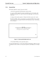
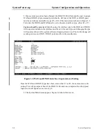
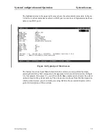
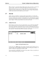
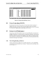
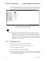
The highlighted area in the upper right corner shows the current alarm status data. In Figure
3-6 below, a yellow alarm has occurred on WAN port 4, and a Loss of Signal alarm has been
detected on WAN port 3.
Figure 3-6.Typical port Main Screen
The bottom line of each port Main Screen lists other actions you can perform by simply
pressing the letter key that corresponds to the uppercase letter of your desired action. In Figure
3-6, for example, if you press “s”, you will invoke the Save command, which saves the current
option settings in the system’s memory. The actions you can choose from this line depend on
which port and screen you are currently accessing. Refer to the associated chapters in this
guide for descriptions of those actions.
Summary of Contents for IMA CS-200 System
Page 18: ...8 Table of Contents Model No Running Head Table of Contents...
Page 22: ...4 List of Figures Model No Running Head List of Figures...
Page 130: ...4 46 General Features Model No Running Head CPU Troubleshooting IMACS 200 General Features...
Page 148: ...5 18 WAN Ports Model No Running Head WAN port Troubleshooting WAN ports...
Page 202: ...9 14 High Speed Data Ports Model No Running Head...
Page 208: ...10 6 OHSU Ports Model No Running Head...
Page 230: ...12 16 IPR Model No Running Head IPR Configuration Screens and Settings IP Routing...
Page 264: ...A 12 System Standards and Specifications Model No Running Head IPR Server Specifications...
Page 274: ...B 10 Error Messages Model No Running Head...
Page 294: ...20 Glossary Model No Running Head Zero Code Suppression...


