Zhone Technologies, Inc.
IMACS Product Book, Version 4
March 2001
Page 15
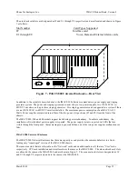
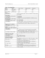
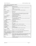
The nine back card slots are designated as IF and U1 through U8 respectively and are allocated and shown in Figure
7 as follows:
Slot Number
Card Types Supported
IF
Interface
card
U1 through U8
Voice, Data and External Alarm cards
R1
R2
R3
R4
R5
IF
U2
U1
U3 U4 U5 U6 U7 U8
AC
R
G
R
+
+ +
- -
- C
O
M
VN
VB
VA
Figure 7 - IMACS 800 Universal Enclosure—Rear View
In addition to the card slots described above, the IMACS 800 chassis accommodates a power supply and ringing
generator system. The power and ringing system can consist of up to two power supplies, two 120/240VAC-to-
48VDC Converters, and up to three ringing generators. Five ringing generators can be supported in a system if there
are no 120/240VAC-to-48VDC Converters installed. The maximum power consumption of an IMACS is 125
Watts. Power supplies are inserted into either of the two power slot positions (F1 and F2) from the front of the
chassis.
The IMACS 800, 900 and 600 models support load sharing power redundancy. To achieve redundancy, the
installation of two identical power supplies is required. The power supply status is reported via LEDs that are
visible through the front panel. Alarm messages are generated when one of the two power supplies malfunctions or
fails.
IMACS 900 Universal Enclosure
The IMACS 900 Universal Enclosure has the same capacity as and provides the same module slots in a front-
loading only “repackaged” version of the IMACS 800 chassis.
There are nine slots that are referred to as the “Network” cards and an additional nine (9) that are “User” cards
respectively. CPU card installation and slot allocation is the same as the IMACS 800. The nine network card slots
are allocated the same as the IMACS 800 and are shown in Figure 9. The nine user card slots are designated as IF
and U1 through U8 respectively and are the same as the IMACS 800.
Summary of Contents for IMACS Network Device
Page 1: ...IMACS Product Book...


