Zhone Technologies, Inc.
IMACS Product Book, Version 4
March 2001
Page 22
2. CPU Cards
The CPU card has two micro-controllers, which performs most of the configuration, management, and common
processing for the IMACS. The CPU card provides the interconnection of WAN/User/Server TDM buses through a
bus connect or cross-connect function. The CPU can have flash memory which is used to store configuration
information and facilitates new firmware uploads. The IMACS can have up to 2 CPU cards, which provide
redundant control and switching capabilities. If the primary CPU fails, the standby takes over.
There are two microprocessors on the CPU card. The primary micro-controller on the CPU card does the
configuration and maintenance functions for the IMACS. It is connected through an internal bus to all the
Server/WAN/User cards and the Interface card. It controls the modem, database, serial terminal interfaces, and
Stratum 4 clock configuration contained on the Interface card. The CPU is responsible for configuring the hardware
residing on the cross-connect module (CCM), and configuring hardware on WAN/User cards. It is responsible for
downloading configurations onto intelligent cards through the appropriate configuration interface. Finally, it
accesses each WAN card to process FDL messages. The CPU provides control functionality, however it is the
Interface card that stores the system configuration information.
The second micro-controller handles standard signaling processing for voice applications. It manages both the
digital (bit-robbed) and the analog (48V) signaling capabilities of the IMACS. It has enough throughput and
interfaces to handle the 62 voice channels routed through the A and B buses. The CPU receives signaling from each
analog voice port and in turn processes the data and generates the appropriate signaling bits over the signaling
highway to the WAN cards. The WAN cards then embed the signaling bits into the T1/E1 data stream. It also
processes the signaling from the T1/E1 link to the User cards. The CPU can also customize the format of the
signaling bits. This is an important feature when interfacing with a variety of central office switches and PBXs.
Additionally, the CPU card has an interface to the IMACS’ time slot switching matrix. The switching matrix may
either be a Bus connect (BCON) or Cross Connect (XCON). In the Bus connect configuration, the User bus ports
can be connected to WAN bus ports but not the Server bus. When Cross-connect is used, all the TDM buses are
brought up to the switching matrix, which is able to cross-connect time slots between the incoming and outgoing
buses.
CPU cards can only be installed in the CPU slots. The shelf can be equipped with two CPUs, which form an
active/standby pair. Watchdog timer circuitry on the Interface card helps monitor the active CPU and will activate
the standby CPU if the active CPU fails. The active and standby CPUs communicate directly and the active can
switch to standby by sending a single message. Additionally, a user can manually switch from the active to standby
CPU by initiating a command from the VT-100 console. It is the CPU card, which initializes the system upon
power-up and runs a self-test on all cards plugged into the system. After the initialization procedure, the CPU card
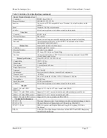
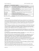
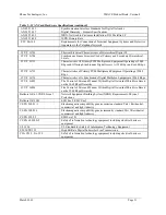
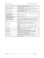
continuously polls all cards in the system to determine their operating status. Table 7 provides detailed
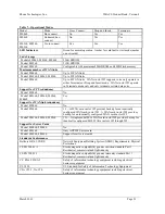
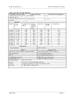
specifications on the five CPU models.
Summary of Contents for IMACS Network Device
Page 1: ...IMACS Product Book...


