background image

Zhone Technologies, Inc. 


IMACS Product Book, Version 4 


March 2001 


Page 38 


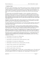
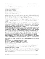
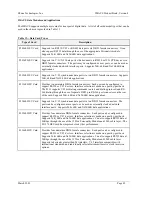
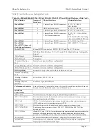
Table 12A—PPO and PPS Line Card Specifications 

Models 812160 and 813160 Eight Channel Line 
Card 


Physical Characteristics


  Model 812160 and 813160 

8 channels 

  Software provisionable options 

Level control and A-Law/Mu law 

  Transport length 

Over 3,000 feet of copper cable at 2W VF ports 

  Out of band signaling  

8 kHz tone, ASK, half duplex 

Voice Transmission


7-bit voice encoding scheme.  LSb used to carry signaling. 

Status Indicators


Loop current, presence or absence at the local end; loss of 
sealing current, far end 

Subscriber and Central Office 
 Interface—Transmit Channel


   Levels received from 2W port 

-2 dBm to +1 dBm 

   Level adjustment 

-3 to +2dB in 0.1 dB increments 


Attenuation distortion (relative to 1 kHz)


-0.5 to +1.0 db, 400 Hz to 2800 Hz 


Idle channel noise


 23 dBrnC


Summary of Contents for IMACS Network Device

Page 1: ...IMACS Product Book...

Page 2: ...PAGE INTENTIONALLY LEFT BLANK...

Page 3: ...ane 14 2 CPU Cards 21 3 Interface Cards 23 4 WAN Cards 27 III Voice Modules and Applications 31 1 FXS 31 2 FXO 32 3 E M 34 4 P Phone 36 5 Voice Channel Bank Application 39 IV Data Modules and Applicat...

Page 4: ...Section Title Page VI Server Cards 65 1 ADPCM 65 2 ISDN 69 3 Management Channel Concentrator MCC 77 4 ACS FRS 79 5 ATM 85 6 Internet Protocol Router 90 7 Low Bit Rate Voice Server 94 VII IMACS System...

Page 5: ...test tone and signaling state generation digital and analog loop back support and remote configuration and control The Server slots on the IMACS platform enable provisioning advanced services such as...

Page 6: ...equipment Flexibility of provisioning technologies using multi bus architecture analog digital packet frame cell etc enables carriers to offer various services and be a one stop provider which generat...

Page 7: ...ut output control and signaling The CPU card employs multiple communication buses extended through the back plane to the User Server WAN and Interface Cards The CPU uses these buses to configure hardw...

Page 8: ...p of eight Time Division Multiplexing TDM highways each 2 048 Mbps in capacity and named W1 1 W1 2 W2 1 W2 2 W3 1 W3 2 W4 1 and W4 2 respectively They are utilized by the WAN cards to format their tra...

Page 9: ...erface card These three cards provide common functions for the shelf The WAN User and Server cards provide the specific data terminal and network interfaces and processing required by the customer to...

Page 10: ...e data can be extracted from selected time slots of T1 E1 WAN links and then expanded by ADPCM Server module This can be accomplished without each WAN card having the hardware required to compress all...

Page 11: ...5 seconds after a CGA declaration or forced OOS command from the User Interface UI The WAN card will remain in the switched condition for 20 seconds or until synchronization can be achieved If synchro...

Page 12: ...nslate from a proprietary messaging format The IMACS uses Embedded SNMP agents to report management information to the manager SNMP is a protocol standard that specifies how management data should be...

Page 13: ...inal Server Router Remote Site 2 Figure 3 IMACS Connectivity to Terminal Servers 1 An alarm occurs in the IMACS on the left side of the diagram and an SNMP trap is sent out the serial port on the inte...

Page 14: ...available on the DS1 frame in the ESF overhead The SA4 bits in the frame alignment word of the E1 constitute the equivalent for E1 This method requires that a DACS II is used in the central office and...

Page 15: ...a can be extracted A B7R card or a MCC card is used in the IMACS at the central site to accept and decode SNMP network management information from up to eight remote IMACS via separate DS0s 128 for MC...

Page 16: ...TS 24 T1 or B4R on TS31 E1 directly via a cross connect or be using FDL T1 SA4 E1 with a DACS version 6 2 or equivalent In addition the MCC card has also four ports configurable with for a variable nu...

Page 17: ...d P Phone Office PPO and one at the Station end P Phone Station PPS Hence PPO and PPS are two user cards designed to support connectivity between a Nortel SL 100 PBX or DMS 100 based Centrex PBX and N...

Page 18: ...er sides respectively There are nine card slots that are accessible from the front and an additional nine that are accessible from the back Card slots are intended to accommodate specific card types a...

Page 19: ...25 Watts Power supplies are inserted into either of the two power slot positions F1 and F2 from the front of the chassis The IMACS 800 900 and 600 models support load sharing power redundancy To achie...

Page 20: ...g is done the same way as the IMACS 800 IMACS 600 Front Load Enclosure The IMACS 600 Universal Enclosure provides card slots only on the front of the unit as shown in Figure 10 This chassis is ideally...

Page 21: ...verter and one ringing generator Physical and Environmental Characteristics The IMACS Universal Enclosure dimensions are shown in Table 1 Table 1 IMACS Dimensions Chassis Height Width Depth Model in c...

Page 22: ...nt Bellcore GR 63 CORE Network Equipment Building System NEBS Level 3 Requirements Physical Protections Bellcore GR 1089 CORE Issue 1 Electrical compatibility and electrical safety generic criteria fo...

Page 23: ...ltage Approvals UL 1459 EN 60950 CSA C22 2 No 950 CE Mark Model 8902 DC Power Supply 48 VDC Input Voltage 39 to 60 VDC Inrush Surge Current Maximum 12 amp at 60VDC Output Power 55 Watts Continuous Max...

Page 24: ...to 24 simultaneously ringing phones Additional ringers can be added depending on the chassis and application see table 5 The exact number of simultaneously ringing subscriber lines supported is a fun...

Page 25: ...Zhone Technologies Inc IMACS Product Book Version 4 March 2001 Page 21 Ventilation Convection cooled Approval UL 1459 CSA C22 2 No 950...

Page 26: ...roughput and interfaces to handle the 62 voice channels routed through the A and B buses The CPU receives signaling from each analog voice port and in turn processes the data and generates the appropr...

Page 27: ...undancy Model 880060 No Model 880460 1 1 A WAN card in slot W2 provides backup for an identically configured WAN card in slot W1 A WAN card in slot W4 provides backup for an identically configured WAN...

Page 28: ...rm system The node port presents an RJ48 female connector with an RS485 electrical interface The Control Terminal port is used to connect a VT100 or compatible terminal to the IMACS system for node ma...

Page 29: ...Card supports the same functionality as the 892360 Interface card except that it has no internal modem port It requires an 880360 CPU and 5 X Y CPU firmware The 892560 Interface card supports one or t...

Page 30: ...92261 8 T1 E1 YES YES YES NO YES 892360 8 T1 E1 YES YES YES YES NO 892460 8 T1 E1 YES YES YES NO NO 892560 2 T1 NO YES YES NO NO 892660 2 T1 YES YES NO YES NO 892760 2 E1 YES YES YES NO NO WAN Ports E...

Page 31: ...892060 892360 892660 only Compatibility ITU T V 22 bis Modulation 16 point QAM Line interface 2 wire balanced 600 ohm Ringer Equivalence 0 2 A Approval FCC Part 68 Equalization Receive automatic adapt...

Page 32: ...F error for the D4 format In an E1 environment an error is defined as any CRC 4 error Controlled Slip or OOF error In the AT T mode two sets of registers user and network accumulate performance data f...

Page 33: ...RU functionality relative to HDSL timing The IMACS can support up to four 4 802060 WAN cards simultaneously and can be configured monitored and tested through the IMACS craft interface and or through...

Page 34: ...030 provides 2 1168Kbps E1 HDSL module Required for each port T1 Signal Format Electrical Interface ANSI T1 102 T1 403 DSX 1 balanced 100 Frame Format D4 ESF Subscriber Loop Carrier SLC 96 SLCD4 Line...

Page 35: ...at 2048 Kbps ITU T G 736 Characteristics of A Synchronous Digital Multiplex Equipment at 2048 Kbps ITU T G 823 The Control of Jitter and Wander Within Digital Networks Which Are Based on the 2048 Kbp...

Page 36: ...fy on a port by port basis whether to use North American ANSI standard ABCD signaling which is the default or ITU CCITT ABCD signaling by turning the signaling conversion setting on or off The trans h...

Page 37: ...XO card for each port programmed for MRD operation Each FXO card provides a single 50 pin female AMPHENOL connector RJ27X All port parameters are software configurable on a port by port basis The Mode...

Page 38: ...2 Dial Pulse E M Caller ID Termination Impedance 600 ohms VF Transmission Characteristics Nominal Transmit TLP Software configurable 10 0dB to 5 0dB steps of 0 1dB Nominal Receive TLP Software configu...

Page 39: ...diagnostics supported on E M cards include the setting of both analog and digital loop backs towards the network and the generation of a Digital MilliWatt signal on a port by port basis A robust set o...

Page 40: ...rier System January 1993 BellCore GR 63 CORE Network Equipment Building System NEBS Requirements Physical Protection ITU T G 712 ITU T Q 552 ITU T Q 553 11 96 Transmission Performance Characteristics...

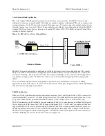
Page 41: ...ffice end also known as P Phone Office PPO and one at the station end referred to as P Phone Station PPS Figure 10 Universal IMACS P Phone Application Nortel CO Switch Line 1 IMACS with PPO Line Card...

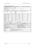
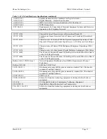
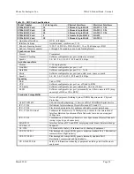
Page 42: ...000 feet of copper cable at 2W VF ports Out of band signaling 8 kHz tone ASK half duplex Voice Transmission 7 bit voice encoding scheme LSb used to carry signaling Status Indicators Loop current prese...

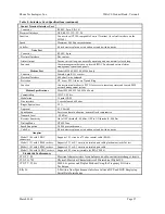
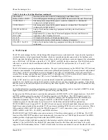
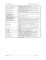
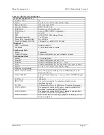
Page 43: ...Sink 960 ohms DC resistance 8 kHz Signaling Specifications Signaling method ASK half duplex carrier only present during transmission of information or acknowledgment Signaling rate 1 kb s half duplex...

Page 44: ...However the existing PSTN may still have analog switches The IMACS is used to convert from robbed bit signaling CAS to analog trunks FXO The voice channel bank platform can be upgraded to provide an...

Page 45: ...onversion features of the IMACS can be used to provide gateway functionality between a DS1 transport network and an E1 transport network See Figure 12b for an illustration of this capability W1 1 W2 1...

Page 46: ...V 25bis dialing commands an in band dialing protocol and RS 366 dialing through the use of separate DB15 pin RS 366 port connectors on the rear of the card Supports 56K 64K and Nx56 64K data applicat...

Page 47: ...backs 822860 BnR Concentrator Card Provides concentration for time slots containing diagnostics from remote IMACS units Multiplexes up to 8 ports of Bit 7 Redundant B7R or B4R formatted data channels...

Page 48: ...ovides TE NT1 and NT2 emulation Commonly used to provide remote extension of four wire BRI CPE devices from an ISDN PBX Requires external power connection 48V DC if more than 3 cards installed in IMAC...

Page 49: ...Additionally if the HSU port is programmed to operate at Nx56 Kbps then RTS will be transmitted end to end and presented as RLSD at the far end of the circuit Software initiated diagnostics support t...

Page 50: ...mergencies can be admitted and support solicited from the Main hospital personnel as shown in Figure 13 Video Codec Main Medical Facility Remote Medical Facility Remote Medical Facility Multichannel C...

Page 51: ...oftware configurable Dial Capability Model 8213 only when used with 8840 PRI Server Card Number of Dialing Ports 2 Dialing Electrical Interface EIA RS 366 ITU T V 25 bis Dialing Physical Interface 2 f...

Page 52: ...ailable at speeds of 2 4 Kbps up to 38 4 Kbps while for asynchronous the range is 300 bps up to 38 4 Kbps Each synchronous port can receive timing from either the DTE device or the system clock If the...

Page 53: ...Card Application The SRU card also supports X 50 division 3 an ITU CCITT standard for sub rate multiplexing The maximum bandwidth of the SRU card is 115 2Kbps The SRU card provides the ability for sof...

Page 54: ...configurable per port on off tied to RTS CTS delay Software configurable per port immediate 30 60 or 100 ms RLSD Software configurable per port permanently on follows remote RTS drop on receipt of IDL...

Page 55: ...sub addressing is transparent to the Frame Relay Transport Network and allows multiple ports on a single FRAD to share the same PVC resulting in lower costs The FRAD card also maintains performance s...

Page 56: ...Zhone Technologies Inc IMACS Product Book Version 4 March 2001 Page 52 Router IMACS w FRAD DACS PSTN Frame Relay PBX Figure 15 IMACS FRAD Card Application...

Page 57: ...Format V 14 or proprietary Stop Bits Software configurable per port 1 or 2 Data Bits Software configurable per port 5 6 7 or 8 Parity Software configurable per port none odd even space or mark Speeds...

Page 58: ...on of other independent low speed data The specification table shows the secondary channel rates associated with the standard primary port rates of the OCU DP card The 8249 OCU DP card also supports t...

Page 59: ...ck of the 4 wire interface of the remote CSU device back towards the network Loop backs of the 4 wire interface of the local CSU device towards the network An OCU DP port may be programmed to detect a...

Page 60: ...ne Loss Limit 19 Ga 22 Ga 24 Ga 26 Ga Rate Rate Rate dB KF KF KF KF 2400 2400 34 133 0 90 7 71 5 56 8 2400 133 3200 34 114 3 79 1 61 9 48 7 4800 4800 34 97 6 65 8 51 1 40 2 4800 267 6400 34 86 3 57 5...

Page 61: ...nt for maintaining wire pair performance When used with IMACS WAN and Server Card options the BRI card supports two transmission protocols BRITE for the 826361 826461 models and Zhone Technologies pro...

Page 62: ...eoc is used for sending operations messages between the ISDN switch and NE line units The requirements are specified in TR 829 The performance monitoring portion of this specification will not be impl...

Page 63: ...rformance monitoring processing Features of an NT like line unit LUNT This section outlines the applicable features in TR NWT 000397 The LUNT has the same master DSL transceiver as an NT1 However the...

Page 64: ...en devices Code Alternate Mark Inversion AMI Rate 192 Kbps 100ppm Timing External and internal software configurable Remote NTU Configuration Options for 256x Zhone Technologies and Adtran NTUs Remote...

Page 65: ...ire U interface Yes ANSI T1 601 1992 TR 393 DSL slave transceiver 2 wire U interface Yes ANSI T1 601 1992 TR 393 Sealing current source Yes Sealing current termination DC Test Signature Yes Yes ANSI T...

Page 66: ...ent data from up to 8 remote IMACS onto a single asynchronous SLIP link for connection to a NMS Essentially the 822860 takes IP management data from the 8 B7R formatted DSOs and concentrates it onto a...

Page 67: ...ware configurable per port 5 6 7 or 8 Stop Bits Software configurable per port 1 or 2 Parity Software configurable per port none odd even space or mark Internal Ports Number 8 Protocol DS0 using Bit 7...

Page 68: ...X WAN Protocols Point to Point PPP Frame Relay up to 14 PVCs supported Inverse ARP Data Rates From 56 Kbps to 1 544 T1 or 2 048 Mbps E1 Hardware Interfaces 1 Ethernet 10BaseT LAN 1 Asynchronous serial...

Page 69: ...he Alarm Card The Alarm card model 840160 provides 4 input sensors and 4 output Form C closures It can use either 48VDC or 12VDC to power the input sensors If 12VDC is used care must be exercised not...

Page 70: ...RJ11F Type FXS Loop Start Loop Resistance 2400 Ohm Loop Current 18 mA to 32 mA Termination Impedance 600 Ohm Nominal Transmit TLP 10 0 dB to 5 0 dB in steps of 0 1 dB Nominal Receive TLP 10 0 dB to 2...

Page 71: ...ression rate The ADPCM card uses this scheme for 24Kbps and 40Kbps although it is not included in the standard The ADPCM card can be used in a variety of applications to reduce the number of transmiss...

Page 72: ...e IMACS is able to do this by placing the 2B D signal into 2 25 time slots 1 for each B and 25 16Kbps for the D channel The ADPCM server is used to increase the number of BRI circuits supported per T1...

Page 73: ...witching Center where an IMACS with two ADPCM servers is used to decompress the voice circuits and send them to the switch via four T1s or E1s Figure 22 IMACS In A Wireless Base Station Application Ba...

Page 74: ...with 3 x CPU 2 active with 1 redundant or 3 active 5 x CPU 3active Transcoder Operation Compliant to G 761 Alarm Indication and Fault Handling Standards Compliance ANSI T1 3021989 ANSI T1 302a 1992 A...

Page 75: ...es 24 minus 1 D channel and 239 B D in E1 environments 8 times 30 time slots minus 1 D channel A basic ISDN PRI facility is a T1 link that consists of 23 B channels and 1 D channel 23B D or an E1 link...

Page 76: ...ustomers are subscribing to ISDN services Each customer is using a fractional PRI service Each customer could be directly connected to the ISDN switch which would consume three fractional T1 E1 circui...

Page 77: ...Inbound calls would be handled in a similar manner All inbound calls would be screened by the IMACS PRI Server card Calls destined for the PBX would be routed to the PBX and calls destined for the Vid...

Page 78: ...ure 26 several non ISDN applications are used including analog voice and data applications low speed SNA data and non ISDN PBXs Several ISDN based applications are being used including video conferenc...

Page 79: ...request another call with smaller bandwidth requirements and will monitor the original leased line for presence of data When the router detects that the leased line is back in operation it will switc...

Page 80: ...s a need to support both existing analog modem applications and new digital ISDN connections over the same network facility End users can migrate as needed from analog modems to ISDN sharing the same...

Page 81: ...call is rejected Local Routing From an IMACS perspective devices such as video codecs or PBXs that are directly attached to the system i e do not pass through a carrier network to connect to the syste...

Page 82: ...t Routing Alternate Routing Alternate routing is provided for calls to take an alternate path in the event of a congested or failed primary trunk When there are more than two Primary Rate D channels p...

Page 83: ...ts and Ethernet allowing IP management data of remote IMACS to be terminated onto a local area network The MCC can route between any of its interfaces depending on its configuration In addition to the...

Page 84: ...nation Three of the 131 are high speed interfaces that can either be configured as Nx64 kbps N 1 to 24 for T1 or 1 to 31 for E1 Those interfaces can independently be configured for the Frame Relay pro...

Page 85: ...e up to three Frame Relay server cards in an IMACS chassis in non redundant operation The Frame Relay Server performance figure of 4000 Frames Second was obtained using 64 byte frames The following ha...

Page 86: ...port for physical layer diagnostics In addition it provides network access for a wide range of devices ranging from high speed data interfaces HSU DDS interfaces OCU DP DS0 DP IDSL interfaces BRI and...

Page 87: ...ovider can now add Internet services and native Frame Relay services by simply installing a Frame Relay server in the existing IMACS as shown in Figure 33 There is no significant addition of new hardw...

Page 88: ...provides up to eight IDSL ports over single twisted pair wire There can be up to seven such BRI cards in an IMACS800 900 This arrangement cost effectively replaces external DDS CSU DSU equipment and...

Page 89: ...ts to transport cellular voice and data traffic to the Mobile Switch Center MSC At the MSC a DCS directs the CDPD traffic typically a single DS0 from each of the 96 cell sites to the IMACS at same MCS...

Page 90: ...its access charges from its service provider for its corporate Frame Relay network Typical examples include banks health care providers technology parks etc The branch offices typically subscribe to a...

Page 91: ...ed connectivity to the ATM network the IMACS eliminates the need to run parallel networks for ATM and TDM traffic The ATM Server Card is based on standards adopted by the ATM Forum and the ITU These s...

Page 92: ...affic Data compressed voice and compressed video are amenable to variations in bandwidth and delay requirements and are modeled as VBR traffic Manageability via SNMP and TELNET SNMP and TELNET managea...

Page 93: ...ulti cast to the sites on the ATM network as shown in Figure 38 The ATM servers located at the Major University locations convert the video from ATM to TDM traffic and pass it on to remote sites over...

Page 94: ...and firmware must be included in an IMACS to add ATM Server operation 880360 CPU Control Card with 8 T1 E1 Cross Connect redundant capable 892360 892460 8 T1 E1 Interface card w 128K NVRAM 882060 ATM...

Page 95: ...s Idle Cell Idle or Unassigned TX_RX Scrambling ON OFF Traffic Types CBR VBR AALs AAL1 AAL3 4 AAL5 Number of PVCs 68 VBR 96 CBR with multi user support Performance 4 000 FPS 64bits frame System Capaci...

Page 96: ...ause no spanning tree or learning algorithm is supported and to avoid loops there should be no more than one physical connection between the same nodes The maximum number of MAC addresses supported is...

Page 97: ...ed service arrangements include local voice service long distance service and a data service Internet access is one of the possible data services The potential market for this technology is quite exte...

Page 98: ...the Internet An external firewall can be used for providing and maintaining security when connected to the Internet DACS Figure 39 IP Routing Server For Internet or Intranet Based Services Private In...

Page 99: ...in a non redundant configuration The processor performance figure of 3500 packets second was obtained using 64 byte packets Table 24 describes the IP Routing Server card specifications The following h...

Page 100: ...E M or from T1 E1 WAN links through the IMACS Each LBRV ACELP G 729 voice compression server card supports up to three composite transmission paths at speeds of 64k 128k or 192k by using one two or t...

Page 101: ...ed by the LBRV server for efficient transmission on the leased E1 trunk using frame relay Up to three LBRV servers are used per up to 8 IMACS terminals to compress up to 192 voice channels from the PS...

Page 102: ...3LBRV 3LBRV 3LBRV 3LBRV 3LBRV 3LBRV 3LBRV 3LBRV 3LBRV 3LBRV T1 T1 2X64K Router Router Router Figure 41 LBRV In a Call Center Application Backhauling Voice Application The IMACS equipped with an LBRV s...

Page 103: ...l Server Figure 42 Backhauling Voice Application Extending Voice Access Application The application shown in Figure 43 is similar to the previous one where the LBRV is deployed to utilize the lower sp...

Page 104: ...characters and are case sensitive The ability to change passwords is hierarchical in that someone logging in at a certain access level may change the passwords associated with their own level and the...

Page 105: ...te an external device such as a bell or light Similarly the occurrence of any alarm designated as minor would trigger a different contact and therefore activate a different external indicator The syst...

Page 106: ...nto four categories 1 WAN diagnostics 2 voice diagnostics 3 data diagnostics and 4 cross connect diagnostics WAN Diagnostics Software initiated diagnostics on T1 and E1 WAN aggregates include looping...

Page 107: ...monitor and set the state of the analog leads of any FXS FXO or E M port They can set and monitor the state of the ABCD signaling bits of the digitized voice signal In cross connect systems test funct...

Page 108: ...es Table 27 Diagnostic Capabilities of Data Ports EIA530 HSU 2 port V 35 HSU 2 port EIA530 V 35 HSU 4 port SRU OCU DP 2 5 10 port DS0 DP 4 port LOOP BACKS On Card Loop backs EIA530 HSU 2 port V 35 HSU...

Page 109: ...ed Seconds ES Yes Yes Yes Yes Yes No Severely Errored Seconds SES Yes Yes Yes Yes Yes No Consecutive Severely Errored Seconds CSES Yes Yes Yes Yes Yes No Out of Synchronization Seconds OSS Yes Yes Yes...

Page 110: ...Data Nx64Kbp s Toward WAN 1 Yes Yes Yes Yes Toward WAN 2 Yes Yes Yes Yes Tones Supported Voice Without Singaling Voice With Singaling Single Data DS0 64Kbps Super rate Data Nx64Kbp s 300 Hz Yes Yes Ye...

Page 111: ...se the diagnostic tool kit to systematically troubleshoot the problem on an end to end basis and to identify the faulty sub system even if it is external to the IMACS One way to systematically trouble...

Page 112: ...Connect Element T1 T1 F acility DDS Facility DSU CSU Remote DTE Cross Connect Element T1 OC U DP Figure 1 V 35 V 35 Local D TE V 35 HSU Cross Connect Element T1 T1 F acility DDS Facility DSU CSU Remot...

Page 113: ...its that terminate on OCU DP cards This capability is built into the system software and does not require any special options or expensive external equipment T1 Line Performance Monitoring Performance...

Page 114: ...used to monitor the DS3 physical link the ATM UNI and VBR and CBR circuit characteristics Statistics are gathered in 15 minute increments for a total of 24 hours Collected statistics include DS3 ATM...

Reviews: