Install the MXK
MXK Hardware Installation Guide
45
9
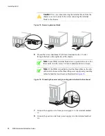
Connect the negative wire from power supply B to the terminal marked
–B.
10
Connect the positive wire from power supply B to the terminal marked
B+.
Note:
If using a single power source, place jumpers between
terminals –VA and –VB.
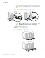
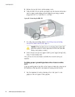
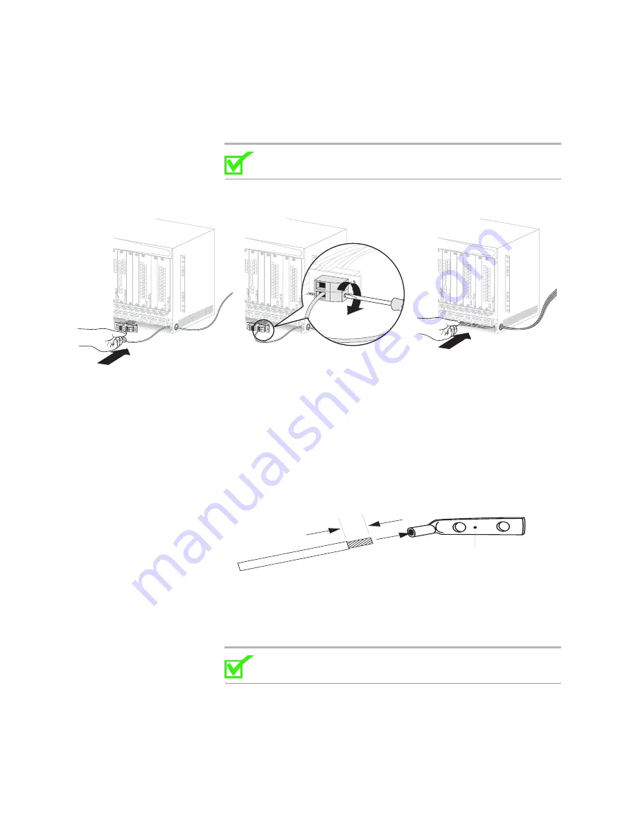
Figure 17: Connecting power cables
11
Reinstall the terminal block into the chassis.
12
Secure the terminal block to the chassis.
13
Route a conductor (minimum 10 AWG and maximum size # 6 wire) from
each chassis to a common 2 AWG frame ground collector that connects to
the single point building ground in an IBN. Be sure that all ground
connections are bare metal to bare metal.
14
Strip the conductor (minimum 10 AWG and maximum size # 6 wire) and
crimp a grounding lug to the end of the conductor.
15
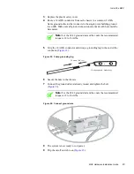
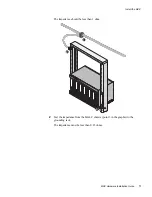
Attach the ground lug to the grounding lugs, as shown in
16
Secure the hex bolts to the chassis.
Note:
For the # 8-32 ground stud and hex nuts the recommended
torque is 12 to 16 in/lbs.
17
Connect the ground cable(s) routed in
and tighten the bolt.
mx0711
13 mm (0.5 in.)
Crimp-type 2-hole lug
FW-10119


